Anti-blocking drainage device for thoracic surgery department

A thoracic surgery and anti-blocking technology, applied in the direction of suction equipment, etc., can solve the problems of not being able to handle gas and liquid separately, increase patient pain, and reduce the practicability of the device, so as to achieve simple structure and operation, reduce labor intensity, and improve practicability Effect

Inactive Publication Date: 2021-11-05
刘顺兰
View PDF0 Cites 0 Cited by
  • Summary
  • Abstract
  • Description
  • Claims
  • Application Information

AI Technical Summary

Problems solved by technology

[0002] At present, most of the existing anti-blocking drainage devices for thoracic surgery have complex structures and operations, and the gas and liquid in the patient's thorax are repeatedly sucked through the syringe, thereby increasing the pain of the patient and improving the labor intensity of the me

Method used


Image

  • Anti-blocking drainage device for thoracic surgery department
  • Anti-blocking drainage device for thoracic surgery department
  • Anti-blocking drainage device for thoracic surgery department

Examples


Example Embodiment

[0028] Example 1:

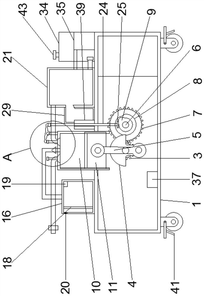
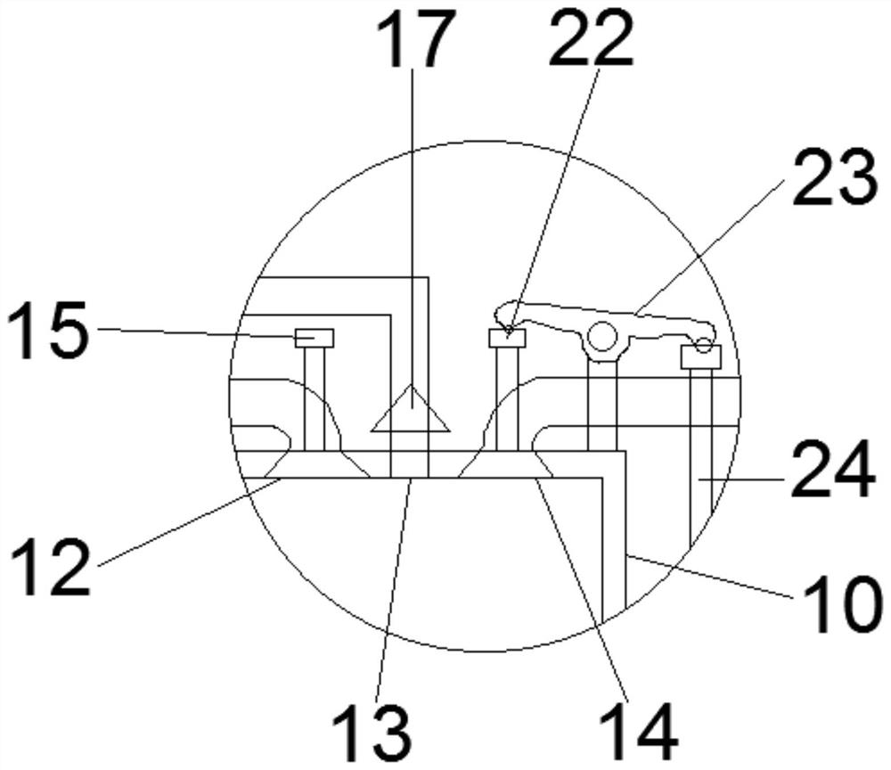
[0029] see Figure 1-8, according to an embodiment of the present invention, an anti-blocking and drainage device for thoracic surgery includes a workbench 1, a first motor 2 is fixed on one side of the workbench 1, and the rotating shaft of the first motor 2 extends into the workbench In the table 1, a first gear 3 is fixedly sleeved in the middle of the rotating shaft of the first motor 2, and a first cam 4 is fixed at one end of the first motor 2. The lower end of the first cam 4 passes through the first gear. The bearing is provided with a connecting rod 5, and a rotating shaft 6 matching the first motor 2 is embedded on one side of the worktable 1 through a second bearing. The middle of the rotating shaft 6 is fixedly sleeved with the first The second gear 7 matched with the gear 3, the first gear 3 and the second gear 7 mesh with each other, a turntable 8 is fixedly sleeved on one side of the rotating shaft 6, and one side of the rotating shaft 6 is ...

Example Embodiment

[0031] Embodiment 2:

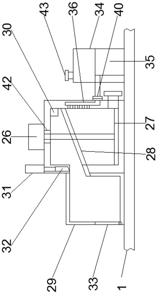
[0032] see Figure 1-4 and Figure 8 , for the sliding sleeve, the upper end of the worktable 1 is fixedly provided with a sliding sleeve 39 matching the sliding rod 24, the rod passes through the sliding sleeve 39, and for the flange, the water pipe passes through the method The flange 40 is connected to the pipe 36 .

[0033] Through the above solution of the present invention, by arranging the sliding sleeve 39 and the flange 40, the movement trajectory of the sliding rod 24 can be easily fixed, and the connection and disassembly of the water pipe and the pipeline 36 can be facilitated.

Example Embodiment

[0034] Embodiment three:

[0035] see Figure 1-4 , for the universal wheel, the four corners of the lower end of the worktable 1 are fixed with universal wheels 41, for the sealing sleeve, the upper end of the push plate 11 is fixedly provided with a sealing sleeve 42, and the upper end of the liquid collecting tank 21 is fixed with a sealing sleeve 42. A sealing sleeve 42 matching the second motor 26 is fixedly provided.

[0036] Through the above solution of the present invention, by providing the universal wheel 41 and the sealing sleeve 42 , the moving device can be facilitated, and the pumping box 10 and the liquid collecting box 21 can be easily sealed.


PUM


Abstract

The invention discloses an anti-blocking drainage device for the thoracic surgery department, the device comprises a workbench, a first motor is fixedly arranged on one side of the workbench, a rotating shaft of the first motor extends into the workbench, the middle of the rotating shaft of the first motor is fixedly sleeved with a first gear, a first cam is fixedly arranged at one end of the first motor, a connecting rod is arranged at the lower end of one side of the first cam through a first bearing, and a rotating shaft matched with the first motor is embedded in one side of the workbench through a second bearing. The anti-blocking drainage device has the advantages that the structure and operation are simple, the anti-blocking drainage device directly enters the thoracic cavity at a time through a drainage pipe, so that pain of a patient is relieved, the labor intensity of medical staff is relieved, collected gas and liquid can be treated separately, and filter residues in the collection box can be flushed reversely in time, so that the labor intensity of the user is further reduced, and meanwhile, the practicability of the device is improved.

Description

technical field [0001] The invention relates to the field of anti-blockage drainage devices for thoracic surgery, in particular to an anti-blockage drainage device for thoracic surgery. Background technique [0002] At present, most of the existing anti-blocking drainage devices for thoracic surgery have complex structures and operations, and the gas and liquid in the patient's thorax are repeatedly sucked through the syringe, thereby increasing the pain of the patient and improving the labor intensity of the medical staff, and The collected gas and liquid cannot be treated separately, and the filter residue in the collection box cannot be disposed of in time during processing, and the collection box cannot be backwashed, which further increases the labor intensity of the user and reduces the device. practicality. [0003] Aiming at the problems in the related technologies, no effective solution has been proposed yet. Contents of the invention [0004] The purpose of t...

Claims


Application Information

Patent Timeline
IPC IPC(8): A61M1/00
Inventor 不公告发明人
Owner 刘顺兰
Why Eureka
Try Eureka