Welding method for thick-wall square steel pipe butt joint

A technology of butt joints and welding methods, applied in welding equipment, welding accessories, characteristics of welding rods, etc., can solve the problems of poor root forming, welding penetration, welding flash, etc., and achieve the improvement of welding efficiency, good appearance and improved fatigue life. Effect

Pending Publication Date: 2021-11-05
青岛中车四方轨道车辆有限公司
9 Cites 0 Cited by

AI-Extracted Technical Summary

Problems solved by technology

[0003] When welding thick-walled square steel pipes, MAG welding often has poor root formation, which is prone to weld penetration, welding lumps, etc., and the full penet...

Abstract

The invention discloses a welding method for a thick-wall square steel pipe butt joint. The welding method comprises the steps that a to-be-welded face of the square steel pipe butt joint comprises an arc-shaped section and a linear section, wherein the arc-shaped section and the linear section are connected end to end, and grooves are formed in the arc-shaped section and the linear section; the to-be-welded face of the square steel pipe butt joint and a to-be-welded face of an adjacent square steel pipe butt joint are assembled in a clearance butt joint mode; horizontal positioning welding is carried out on the grooves; bottoming welding from vertical welding to flat welding is carried out on the arc-shaped section by adopting TIG welding, and TIG welding bottoming welding is carried out on the linear section from a bottoming welding flat welding position of the arc-shaped section; filling welding from vertical welding to flat welding is carried out on the arc-shaped section by adopting MAG welding, and MAG welding filling welding is carried out on the linear section from a filling welding flat welding position of the arc-shaped section; and cosmetic welding from vertical welding to flat welding is carried out on the arc-shaped section by adopting MAG welding, and MAG welding cosmetic welding is carried out on the linear section from a cosmetic welding flat welding position of the arc-shaped section. According to the welding method for the thick-wall square steel pipe butt joint, full penetration of a circular arc transition position of a thick-wall square pipe is guaranteed, and the fatigue life of the square pipe butt joint is prolonged.

Application Domain

Electrode holder supportersWelding accessories

Technology Topic

Image

  • Welding method for thick-wall square steel pipe butt joint
  • Welding method for thick-wall square steel pipe butt joint
  • Welding method for thick-wall square steel pipe butt joint

Examples

  • Experimental program(1)

Example Embodiment

[0033] The technical solutions in the embodiments of the present application will be clearly and completely described below with reference to the drawings in the embodiments of the present application. Obviously, the described embodiments are only a part of the embodiments of the present application, but not all of the embodiments. Based on the embodiments in the present application, all other embodiments obtained by those of ordinary skill in the art without creative efforts shall fall within the protection scope of the present application.
[0034] In the description of this application, it should be understood that the terms "center", "upper", "lower", "front", "rear", "left", "right", "vertical", "horizontal", The orientation or positional relationship indicated by "top", "bottom", "inner", "outer", etc. is based on the orientation or positional relationship shown in the drawings, and is only for the convenience of describing the present application and simplifying the description, rather than indicating or implying The device or element referred to must have a particular orientation, be constructed and operate in a particular orientation, and therefore should not be construed as a limitation of the present application.
[0035] The terms "first" and "second" are only used for descriptive purposes, and should not be construed as indicating or implying relative importance or implicitly indicating the number of technical features indicated. Thus, a feature defined as "first" or "second" may expressly or implicitly include one or more of that feature. In the description of this application, unless stated otherwise, "plurality" means two or more.
[0036] In the description of this application, it should be noted that, unless otherwise expressly specified and limited, the terms "installed", "connected" and "connected" should be understood in a broad sense, for example, it may be a fixed connection or a detachable connection Connection, or integral connection; can be mechanical connection, can also be electrical connection; can be directly connected, can also be indirectly connected through an intermediate medium, can be internal communication between two elements. For those of ordinary skill in the art, the specific meanings of the above terms in this application can be understood in specific situations.
[0037] In the present invention, unless otherwise expressly specified and limited, a first feature "on" or "under" a second feature may include the first and second features in direct contact, or may include the first and second features Not directly but through additional features between them. Also, the first feature being "above", "over" and "above" the second feature includes the first feature being directly above and obliquely above the second feature, or simply means that the first feature is level higher than the second feature. The first feature is "below", "below" and "below" the second feature includes the first feature being directly below and diagonally below the second feature, or simply means that the first feature has a lower level than the second feature.
[0038] The following disclosure provides many different embodiments or examples for implementing different structures of the present invention. In order to simplify the disclosure of the present invention, the components and arrangements of specific examples are described below. Of course, they are only examples and are not intended to limit the invention. Furthermore, the present disclosure may repeat reference numerals and/or reference letters in different instances, such repetition is for the purpose of simplicity and clarity and does not in itself indicate a relationship between the various embodiments and/or arrangements discussed. In addition, the present disclosure provides examples of various specific processes and materials, but one of ordinary skill in the art will recognize the application of other processes and/or the use of other materials.
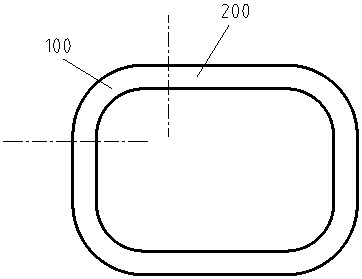
[0039] Step 1, such as figure 1 As shown, the to-be-welded surface of the square steel pipe butt joint includes an arc section 100 and a straight section 200, the arc section 100 and the straight section 200 are connected end to end, and both the arc section 100 and the straight section 200 are beveled.
[0040] Step 2. The to-be-welded surface of the square steel pipe butt joint and the to-be-welded surface of the adjacent square steel pipe butt joint are butt-jointed and assembled; the assembly gap generally needs to be kept within the range of 3mm-4mm, and the angle of the groove is 60 degrees. At the same time, it is necessary to ensure that both sides of the joint are parallel, and the deviation is less than 1mm.
[0041] Step 3. Perform horizontal positioning welding on the groove; after the horizontal positioning welding, grind both ends of the weld.
[0042]Step 4, using TIG welding to perform bottoming welding of vertical welding to flat welding on the arc section 100 . The TIG welding process can make the root get good penetration, and the penetration is uniform, and the surface is smooth and neat. The vertical welding position adopts the upper crescent transportation method, and the flat welding position adopts the rear crescent transportation method, so as to avoid the non-fusion between layers and ensure good fusion. The flat welding should be extended to the straight section 200, so that the starting end to the end of the weld after bottoming welding crosses the arc section 100, keep the weld joint on the straight section 200, and avoid the weld joint at the arc section 100, Thus, the welding quality at the arc section 100 is guaranteed. The straight section 200 is welded by TIG welding. TIG priming welding can obtain uniform penetration, smooth surface and neat joint root, avoiding the generation of stress concentration.
[0043] In order to prevent problems such as burn-through during filling welding in the subsequent step 5, a multi-layer welding method can be used for bottoming welding.
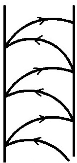
[0044] Step 5, using MAG welding to perform filler welding from vertical welding to flat welding on the arc section 100 . The appearance of the weld seam is good, and the welding efficiency is high. The vertical welding position adopts the method of moving the bar on the crescent, and the welding torch is as follows: figure 2 Swing sequentially in the direction of the arrows shown; the flat welding position adopts the rear crescent transport method, and the welding torch is as follows image 3 The directions of the arrows shown are swung sequentially to avoid unfusion between layers and ensure good fusion. The flat welding is extended to the straight section 200 , so that the start end to the end of the fill-welded weld spans the arc section 100 , keeping the joint on the straight section 200 , thereby ensuring the welding quality at the arc section 100 . The straight section 200 is welded by MAG welding, and the filling welding of the straight section 200 starts from the flat welding position of the arc section 100 to the flat welding position of another arc section 100 adjacent to the straight section 200 .
[0045] According to the thickness of the square steel pipe, multi-layer filling welding can be used. After each layer of weld bead is welded, the start and end defects of the weld bead need to be polished.
[0046] Step 6, using MAG welding to perform cover welding of vertical welding to flat welding on the arc section 100 . like figure 2 , image 3 As shown, the appearance of the weld seam is good and the welding efficiency is high using the MAG welding process. The vertical welding position adopts the method of moving the bar on the crescent, and the welding torch is as follows: figure 2 Swing sequentially in the direction of the arrows shown; the flat welding position adopts the rear crescent transport method, and the welding torch is as follows image 3 The directions of the arrows shown are swung sequentially to avoid unfusion between layers and ensure good fusion. The flat welding is extended to the straight section 200 , so that the start end to the end of the welded seam after the cover welding crosses the arc section 100 , and keeps the joint on the straight section 200 , thereby ensuring the welding quality at the arc section 100 . The straight section 200 is covered by MAG welding. The cover of the straight section 200 is welded from the flat welding position of the arc section 100 to the flat welding position of another arc section 100 adjacent to the straight section 200 .
[0047] During the welding of step 4, step 5 and step 6, the start and end positions of the welds of each adjacent two layers of welds are staggered by 10-20mm, so as to avoid the large welding seam caused by the welds of the two adjacent layers being in the same position. The cumulative error of size causes obvious stress concentration.
[0048] After step 4, step 5 and step 6, the composite welding method of TIG bottoming + MAG filling cover can be used to make the weldment better adapt to the working conditions of alternating load and meet the designed fatigue strength.
[0049] The full penetration welding of the butt joint weld of the thick-walled square steel pipe is realized through the multi-section multi-welding position and the composite welding method, especially the full penetration of the 100 transition of the arc section of the square steel pipe is guaranteed, and the welding seam of the square steel pipe butt joint is improved. fatigue life.
[0050] Welding conditions such as current, voltage and other parameters that affect the welding process of MIG welding are called welding specifications. The arc section 100 is bottomed by TIG welding, and the welding parameter is a current of 100-135.
[0051] The arc-shaped section 100 uses small standard welding for vertical welding to flat welding and cover welding, and the welding parameters are current 120-145A and voltage 18-22V. The vertical welding method here is vertical welding, and the vertical welding method usually adopts small specification welding to avoid the occurrence of burn-through and downflow. The filling welding and cover welding of the straight section 200 adopts large-scale welding, and the welding parameters are the current of 220-320A and the voltage of 23-32V. The straight section 200 is welded by a large standard welding method, which can improve the welding efficiency and ensure fusion. The specific welding parameters are shown in Table 1. The definition of arc segment small specification welding and straight segment large specification welding in Table 1 is only for MAG welding.
[0052] Table 1 Welding parameters of arc section and straight section of square steel pipe
[0053]
[0054] After the welding is completed, the surface of the weld shall be cleaned and the welding quality shall be inspected. The root of the weld is detected by endoscope. After the appearance of the weld, the surface of the weld is detected by magnetic particle inspection. Finally, the fusion condition inside the weld is detected by radiography. In order to verify the welding process and confirm the performance of welded joints, destructive tests such as tensile, bending, impact, hardness and macroscopic tests are carried out, and non-destructive testing of VT MT and RT is carried out before sampling.
[0055] In the foregoing description of the embodiments, the particular features, structures, materials or characteristics may be combined in any suitable manner in any one or more of the embodiments or examples.
[0056] The above are only specific embodiments of the present invention, but the protection scope of the present invention is not limited thereto. Any changes or substitutions that can be easily thought of by those skilled in the art within the technical scope disclosed by the present invention should be covered. within the protection scope of the present invention. Therefore, the protection scope of the present invention should be subject to the protection scope of the claims.

PUM

no PUM

Description & Claims & Application Information

We can also present the details of the Description, Claims and Application information to help users get a comprehensive understanding of the technical details of the patent, such as background art, summary of invention, brief description of drawings, description of embodiments, and other original content. On the other hand, users can also determine the specific scope of protection of the technology through the list of claims; as well as understand the changes in the life cycle of the technology with the presentation of the patent timeline. Login to view more.

Similar technology patents

Classification and recommendation of technical efficacy words

  • Improve fatigue life
  • Well formed appearance

Method for preparing low-heat-generation fatigue-resistant vulcanized rubber

InactiveCN101519510AImprove fatigue lifeImprove the processing environmentButadiene-styrene rubberStearic acid
Owner:SHENYANG INSTITUTE OF CHEMICAL TECHNOLOGY

A peen forming method for a ribbed structure

ActiveCN101530959AImprove fatigue lifeIncrease the amount of shot peening deformationPeeningDistortion
Owner:AVIC BEIJING AERONAUTICAL MFG TECH RES INST

Vacuum electron beam welding method for magnesium alloy component

ActiveCN111545890AWell formed appearanceHigh consistency of welding qualityElectron beam welding apparatusVacuum electronicsSeam welding
Owner:CHINA WEAPON SCI ACADEMY NINGBO BRANCH
Why Eureka
Try Eureka