Construction technology of side top framework with deflection set through welding

A construction process and side roof technology, applied in the field of rail vehicles, can solve the problems of complex welding fixture deflection settings, affecting the assembly accuracy of the side roof frame, and difficulty in maintenance and overhaul, so as to speed up the project progress, reduce the difficulty of debugging, and reduce the difficulty of installation and construction. simple effect

Active Publication Date: 2021-11-05
天津中车唐车轨道车辆有限公司 +1
View PDF3 Cites 0 Cited by
  • Summary
  • Abstract
  • Description
  • Claims
  • Application Information

AI Technical Summary

Problems solved by technology

[0004] But currently there are the following deficiencies: (1) The design of the welding jig itself with preset deflection is flawed; The support surface of the welding fixture is also a contoured arc surface support, and these arc surface supports will not deviate in the interface position between the support and the support when they are arranged in a straight line
However, when arranged according to the deflection curve, because the arc surface supported by the arc surface is a spatial surface, there will be a little misalignment, which will affect the assembly accuracy of the side roof frame, and the assembly of parts is also very difficult; (2) the welding fixture The deflection setting is very complicated. It must conform to the deflection curve and fine-tune to reduce the gap between the arc supports. The adjustment is very complicated, and the maintenance and repair are also very difficult, requiring a lot of manpower and material resources.

Method used


Image

  • Construction technology of side top framework with deflection set through welding
  • Construction technology of side top framework with deflection set through welding
  • Construction technology of side top framework with deflection set through welding

Examples


Embodiment Construction

[0047] It should be noted that, in the case of no conflict, the embodiments of the present invention and the features in the embodiments can be combined with each other.

[0048] In describing the present invention, it should be understood that the terms "center", "longitudinal", "transverse", "upper", "lower", "front", "rear", "left", "right", " The orientations or positional relationships indicated by "vertical", "horizontal", "top", "bottom", "inner" and "outer" are based on the orientations or positional relationships shown in the drawings, and are only for the convenience of describing the present invention and Simplified descriptions, rather than indicating or implying that the device or element referred to must have a particular orientation, be constructed and operate in a particular orientation, and thus should not be construed as limiting the invention. In addition, the terms "first", "second", etc. are used for descriptive purposes only, and should not be understood ...


PUM


Abstract

The invention provides a construction technology of a side top framework with deflection set through welding. The construction technology comprises the following steps that S1, a welding shrinkage state measurement test of a lower edge beam is designed according to the welding form of the lower edge beam and a side top camber beam of the side top framework; S2, a side top framework short module simulation test is designed according to the prefabricated deflection needed by the side top framework and the shrinkage amount of the lower edge beam; S3, the flexural deflection of a side top framework short module after welding in the step S2 is measured, and is compared with an expected deflection value of the side top framework; and S4, according to a deflection comparison result in the step S3, the welding process of a whole side top is designed, and the side top framework is manufactured in a trial manner. The construction technology of the side top framework with deflection set through welding is simple, a used tool without preset deflection is simpler than a traditional tool and is convenient to maintain and repair, during side top framework production, installation and construction are easy, operation is convenient, and the manufacturing period is effectively shortened.

Description

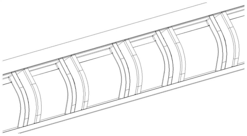
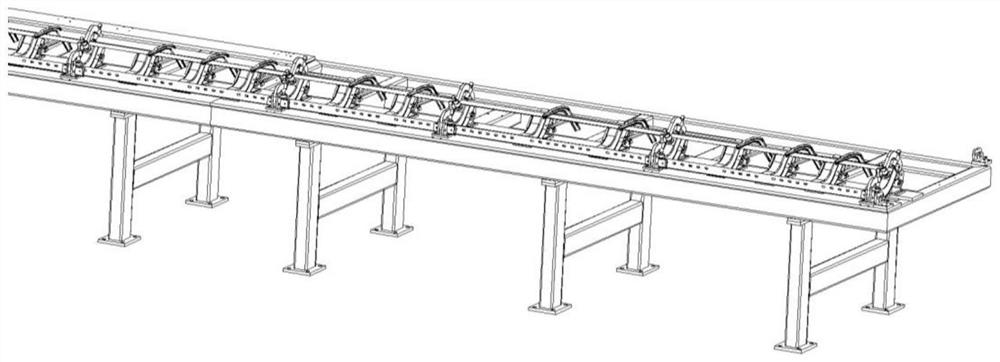
technical field [0001] The invention belongs to the technical field of rail vehicles, and in particular relates to a construction process of a side roof frame in which deflection is set by welding. Background technique [0002] Such as figure 1 As shown, the side roof frame structure is generally composed of three parts: the upper side beam, the lower side beam and the side roof curved beam. The side roof frame needs to preset the deflection during production, and the deflection is mainly achieved through the length direction of the welding fixture. It is realized by setting the deflection, so that the parts welded on the welding jig produce deflection. [0003] At present, most of the presets of the deflection of the side roof frame are realized through the deflection on the welding fixture, such as figure 2 As shown, the details are as follows: (1) by arranging a series of arc-surface support tables that follow the shape of the side roof curved beams in a straight line;...

Claims


Application Information

Patent Timeline
IPC IPC(8): B23K31/02B23K31/12
CPCB23K31/02B23K31/12Y02T30/00
Inventor 许晓航贾鹏郭会生刘艳红姚明哲陈树娟刘楠楠路守暾吴浩张玉峰李彦伟
Owner 天津中车唐车轨道车辆有限公司
Why Eureka
Try Eureka