Electromagnetic lock positioning plate for high-voltage switch equipment and production method of electromagnetic lock positioning plate

A high-voltage switch and electromagnetic lock technology, which is applied to building locks, building structures, and locks controlled by non-mechanical transmissions, can solve the problems of rising electromagnetic lock costs, high manufacturing costs, and large capital occupation, so as to reduce manufacturing costs, The effect of simple and mature process and high qualified rate of finished products

Inactive Publication Date: 2012-07-18
镇江泰源电器科技有限公司
View PDF5 Cites 4 Cited by
  • Summary
  • Abstract
  • Description
  • Claims
  • Application Information

AI Technical Summary

Problems solved by technology

This not only requires the design of two sets of casting molds, but also brings two different types of electromagnetic lock panels that must be stocked, resulting in high manufacturing costs and a large amount of capital.
[0009] 3. Made of high-priced and rising zinc-aluminum alloy materials, the cost of electromagnetic locks for high-voltage switchgear continues to rise

Method used


Image

  • Electromagnetic lock positioning plate for high-voltage switch equipment and production method of electromagnetic lock positioning plate
  • Electromagnetic lock positioning plate for high-voltage switch equipment and production method of electromagnetic lock positioning plate
  • Electromagnetic lock positioning plate for high-voltage switch equipment and production method of electromagnetic lock positioning plate

Examples


Embodiment Construction

[0025] Below in conjunction with accompanying drawing the implementation details of the present invention are described as follows:

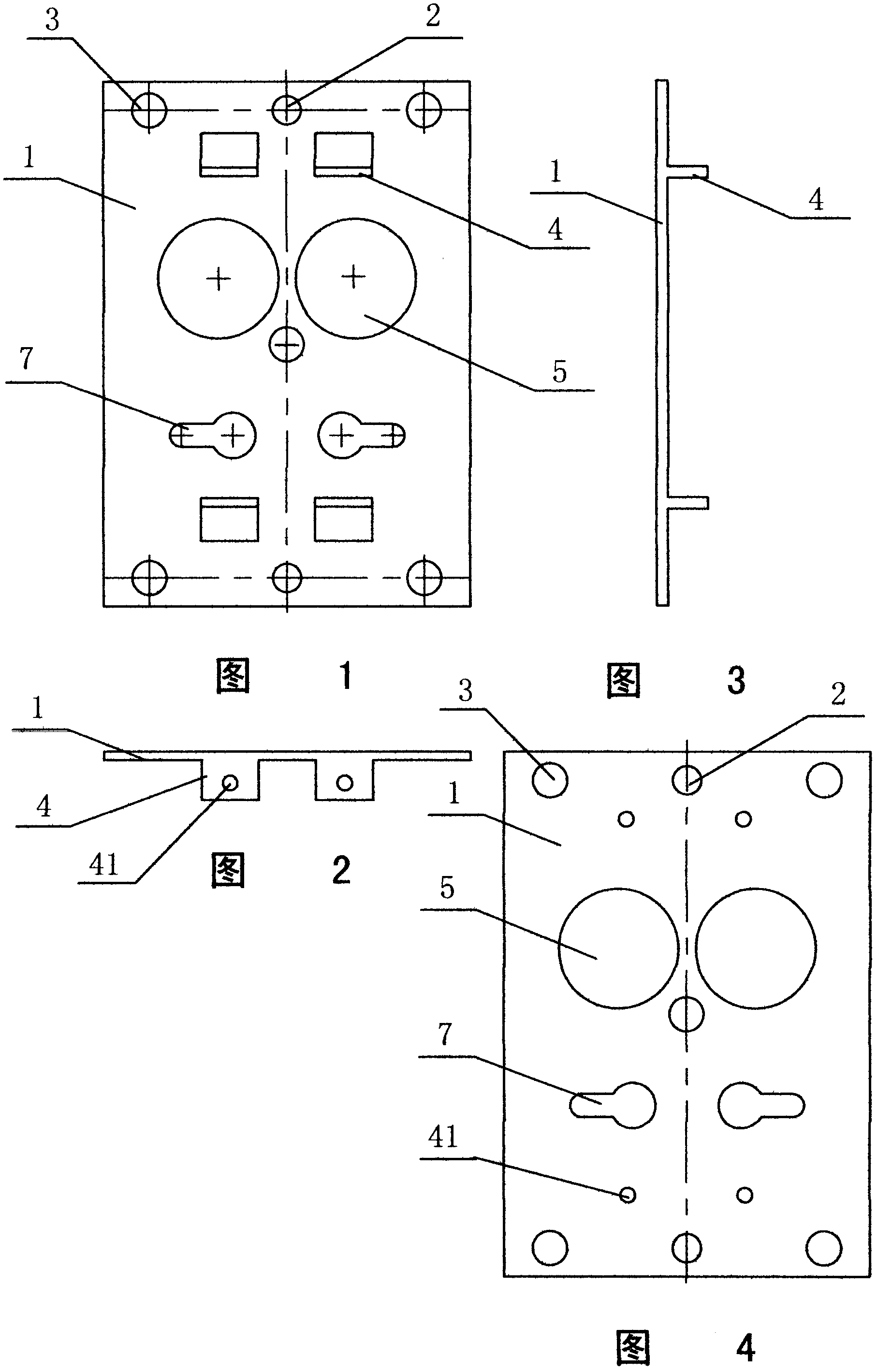
[0026] like figure 1 , 2 . As shown in 3, an electromagnetic locking bit plate for high-voltage switchgear, including a rectangular plate body 1, is located at the upper and lower midpoints of the upper and lower sides of the plate body, and has a screw hole 2 for installing a whole lock, located at the plate body The 4 and 1 connection electromagnetic lock panels at the four corners and the center are embedded holes 3, which are characterized in that the connecting line between the midpoints of the upper and lower sides of the board is the symmetrical axis, and there are two symmetrically distributed ones.

[0027] ——The upper and lower positioning connecting plates 4 perpendicular to the surface of the plate body for connecting the electromagnetic lock housing;

[0028] ——The positioning circular hole 5 corresponding to the handle hole or t...


PUM


Abstract

An electromagnetic lock positioning plate for high-voltage switch equipment and a production method of the electromagnetic lock positioning plate belong to electromagnetic lock parts and production methods. The positioning plate comprises a plate body, screw holes for mounting of locksets and embedding holes for faceplate connection, and is characterized in that positioning connecting plates, positioning round holes and positioning keyholes are symmetrically distributed pairwise with a line, from an upper side midpoint to a lower side midpoint of the plate body, serving as a symmetry axis, wherein the positioning connecting plates with upper screw holes and lower screw holes are connected with an electromagnetic lock shell and perpendicular to the face of the plate body, the positioning round holes correspond to handle holes or displaying holes of indicator lamps, and the positioning keyholes correspond to keyholes of unlocking components. The production method includes: punching all the holes during punching shear of the rectangular plate body, punching shear three sides of each of rectangular upper and lower positioning connecting plates simultaneously, and bending along the fourth sides to enable the fourth sides to be perpendicular to the plate body. Compared with zinc-aluminum alloy thin plate casting in the prior art, the electromagnetic lock positioning plate and the production method have the advantages that process is simple and mature, yield of finished products is up to more than 98%, and production cost is reduced by more than 40%.

Description

technical field [0001] The invention belongs to an electromagnetic lock component and a manufacturing method for a high-voltage switchgear, in particular to an electromagnetic locking position plate for a high-voltage switchgear and a manufacturing method thereof. Background technique [0002] The operation of high-voltage switchgear must be strictly in accordance with the safety operating procedures stipulated by the industry to achieve: prevent the switch from being pulled on by mistake, prevent the isolation switch from being pulled on the load, prevent it from entering the charged interval by mistake, prevent it from being connected to the ground wire when it is charged, and prevent it from being connected to the ground wire. The "five defenses" requirements for closing. The existing electromagnetic locks for various high-voltage switchgears are just in line with the requirements of this specification. With the cooperation of the lockset and the mechanical structure of t...

Claims


Application Information

Patent Timeline
IPC IPC(8): E05B15/00B21D35/00B21D28/02B21D28/24B21D5/00E05B47/00
Inventor 牛龙华
Owner 镇江泰源电器科技有限公司
Why Eureka
Try Eureka