MEMS (Micro-electromechanical Systems) microphone

A microphone and circuit board technology, applied in electrostatic transducer microphones and other directions, can solve problems such as shortening the service life of MEMS microphones, MEMS microphones not working properly, and damaging MEMS chips, improving acoustic performance, reducing the probability of being damaged, The effect of prolonging the service life

Active Publication Date: 2013-06-26
WEIFANG GOERTEK MICROELECTRONICS CO LTD
View PDF4 Cites 6 Cited by
  • Summary
  • Abstract
  • Description
  • Claims
  • Application Information

AI Technical Summary

Problems solved by technology

[0003] The disadvantage of the MEMS microphone with this structure is: because the structure of the MEMS chip is that the diaphragm is on the bottom and the back plate is on the top, there is no shield between the diaphragm and the sound hole, and it is easy to damage the membrane when the airflow entering the sound hole is strong. chip, thus damaging the MEMS chip, resulting in the failure of the MEMS microphone to work normally, and shortening the service life of the MEMS microphone

Method used


Image

  • MEMS (Micro-electromechanical Systems) microphone
  • MEMS (Micro-electromechanical Systems) microphone
  • MEMS (Micro-electromechanical Systems) microphone

Examples


Embodiment 1

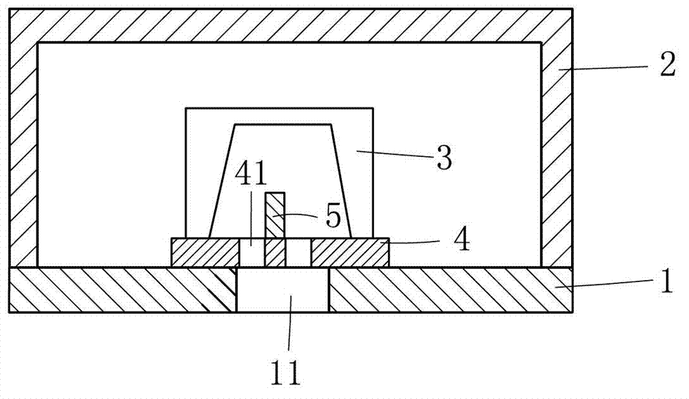
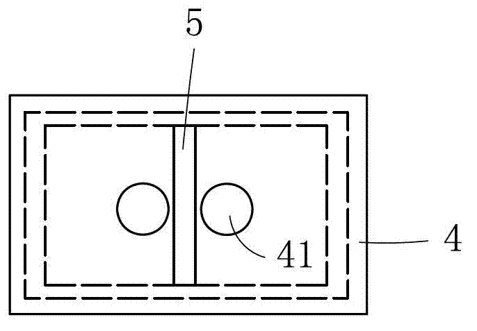
[0025] Such as figure 1 and figure 2 Commonly shown, a kind of MEMS microphone comprises the housing 2 that is made by metal material or circuit board material, and housing 2 is the cylindrical structure that one end is open and one end is closed, and the open end of housing 2 is combined with circuit board 1, and circuit board 1 and The combined side of the shell 2 is the inner side of the circuit board 1 , and the center of the circuit board 1 is provided with a first sound hole 11 , and the diameter of the first sound hole 11 is 0.25±0.05 mm. The inner side of the circuit board 1 corresponding to the first sound hole 11 is bonded with a support member 4. The support member 4 is a flat plate structure. Two second sound holes 41 are arranged on the support member 4. The aperture of the second sound hole 41 is 0.01- 0.1 mm, the diameter of the second acoustic hole 41 in this embodiment is preferably 0.03-0.05 mm, the two second acoustic holes 41 are located in the orthograp...

Embodiment 2

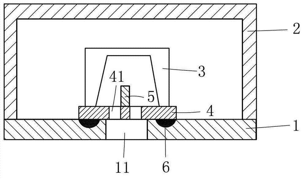
[0031] Such as image 3 As shown, this embodiment is basically the same as Embodiment 1, the difference is:

[0032]A glue overflow groove 6 is provided on the circuit board 1 at the position where the support member 4 is attached to the circuit board 1 . When the support member 4 is pasted and combined with the circuit board, the excess glue can easily block the sound hole, and the excess glue groove 6 can collect the excess glue, which effectively solves the problem that the sound hole is easily blocked, and improves the performance of the MEMS microphone. Finished product pass rate.

[0033] The overflow groove 6 corresponds to the edge of the support 4, and the edge of the support 4 is far away from the first sound hole 11 and the two second sound holes 41, further preventing the sound holes from being blocked.

Embodiment 3

[0035] Such as Figure 4 As shown, this embodiment is basically the same as Embodiment 1, the difference is:

[0036] A groove is provided on the circuit board 1 corresponding to the position of the support member 4 , the support member 4 is pasted in the groove, and a part of the support member 4 protrudes from the plane of the circuit board 1 .

[0037] Compared with the first embodiment, this embodiment makes full use of the thickness of the circuit board 1 to reduce the space occupied by the support member 4 in the z-axis direction, which can make the MEMS microphone thinner and is suitable for thin products.


PUM


Abstract

The invention discloses an MEMS (Micro-electromechanical Systems) microphone, and relates to the technical field of electroacoustic products. The MEMS microphone comprises an outer shell and a circuit board which is combined with the outer shell integrally; the circuit board is provided with a first sound aperture; one side of the circuit board, which is combined with the outer shell, is defined to be the inner side of the circuit board; the inner side of the circuit board, corresponding to the first sound aperture, is provided with an MEMS chip which is installed on the circuit board through a support element; the support element is provided with at least two second sound apertures; the aperture diameter sizes of the second sound apertures are less than the aperture diameter size of the first sound aperture; each second sound aperture is positioned in an orthographic projection of the first sound aperture; and the support element is also provided with a baffle plate for preventing air flows passing through the second sound apertures from interfering mutually. According to the invention, the technical problems that in the prior art, the MEMS chip of the MEMS microphone is easy to damage and the like are solved. The MEMS microphone provided by the invention has the advantages of long service life, high flexibility, good acoustic performance, high finished product percent of pass and the like.

Description

technical field [0001] The invention relates to the technical field of electroacoustic products, in particular to a MEMS microphone. Background technique [0002] With the rapid development of electronic technology, MEMS (micro-electro-mechanical system) microphones have gained popularity due to their small size, easy SMT (surface mount technology) installation, high temperature resistance, good stability, high degree of automation and suitable for mass production. more and more widely used. The MEMS microphone in the prior art usually includes a housing and a circuit board integrated with the housing. The circuit board is provided with a sound hole, and a MEMS chip is provided on the inner side of the circuit board at a position corresponding to the sound hole. The MEMS chip has a structure with the back plate on the top and the diaphragm on the bottom, such as Figure 7 As shown, the base 31 is included, the base 31 is provided with a diaphragm 32, the edge of the diaphra...

Claims


Application Information

Patent Timeline
Patent Type & Authority Applications(China)
IPC IPC(8): H04R19/04
Inventor 王喆王显彬刘诗婧
Owner WEIFANG GOERTEK MICROELECTRONICS CO LTD
Why Eureka
Try Eureka