
Construction elevator

A hoist and lifting plate technology, which is applied in the direction of hoisting devices, lifting frames, mechanical equipment, etc., can solve the problems of small area of ​​force, the inability of grooves to play a role in limiting positions, and the inconvenience of construction personnel taking off pipes, etc., to ensure that The effect of stability

Pending Publication Date: 2021-11-05
高晓斌
View PDF6 Cites 0 Cited by
  • Summary
  • Abstract
  • Description
  • Claims
  • Application Information

AI Technical Summary

Problems solved by technology

[0003] However, with the above technology, only pipes with a specified diameter can be lifted. When the diameter is too large, the groove cannot play a limiting role. When the diameter is too small, the pipe shakes freely in the groove, and rigidity occurs with the inner wall of the groove. Collision, easy to cause damage to the outer wall of the pipe, and there is a risk of the pipe slipping out of the groove
At the same time, the number of pipes to be transported at one time is limited by the area of ​​the placement plate, and the pipes can only be laid in the groove. If multiple pipes are stacked, there is a safety hazard of pipe slippage
And the pipe is located in the groove. When the construction personnel need to remove the pipe from the placement plate, the area of ​​effort is small, and it is inconvenient for the construction personnel to remove the pipe.

Method used


Image

  • Construction elevator
  • Construction elevator
  • Construction elevator

Examples


Embodiment 1

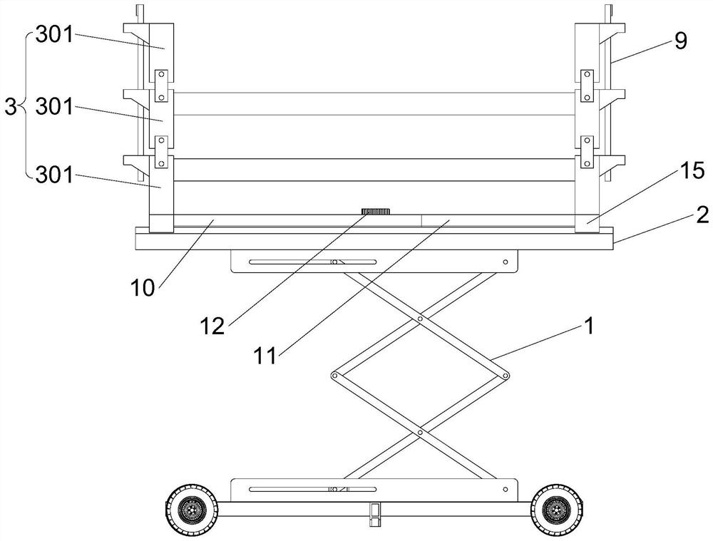
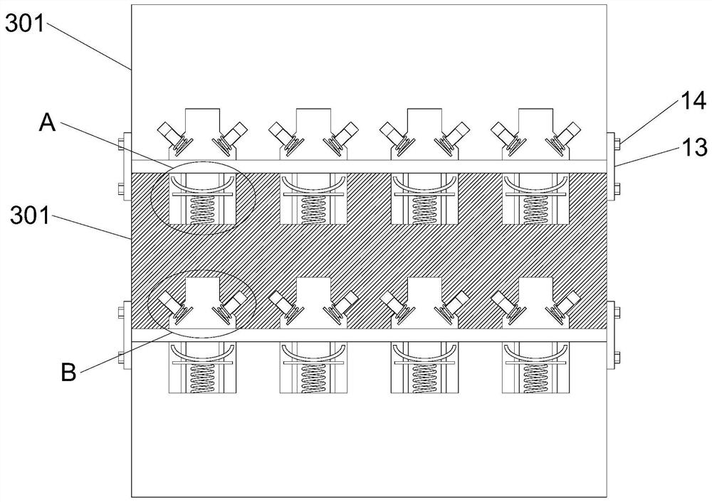
[0035]The construction hoist of the present invention includes a scissor hoist 1, the upper end of the scissor hoist 1 is provided with a placement plate 2, and the upper end of the placement plate 2 is provided with two symmetrical side protection units 3, and the side protection unit 3 includes a plurality of The positioning plates 301 stacked in the vertical direction are hingedly connected between adjacent positioning plates 301, the positioning plate 301 at the top can be turned outward relative to the positioning plate 301 at the bottom, and the upper end of any positioning plate 301 is provided with a first groove 5. An elastic support assembly 4 is provided in the first groove 5, a second groove 6 is provided at the lower end of the positioning plate 301, and an elastic pressing assembly 7 is arranged in the second groove 6, and the elastic pressing assembly 7 located on the upper positioning plate 301 The tightening assembly 7 can cooperate with the elastic support ass...

Embodiment 2

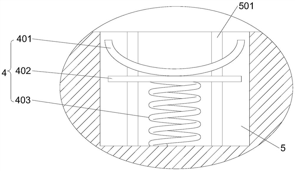
[0038] This embodiment is further optimized on the basis of Embodiment 1 as follows: the elastic support assembly 4 includes a support plate 401, a lift plate 402 and a buffer spring 403, the upper end surface of the support plate 401 is an arc surface, and the lift plate 402 is arranged on the support plate At the lower end of the plate 401 , the buffer spring 403 is located between the support plate 401 and the bottom wall of the first groove 5 . The side wall of the first groove 5 is provided with a chute 501 along the vertical direction, the upper end of the chute 501 runs through the positioning plate 301, and the side wall of the lifting plate 402 is provided with a slide block 502 that is compatible with the chute 501. The cross-sectional shape of the slider 502 is dovetail or T-shaped, and the sliding groove 501 is a dovetail or T-shaped groove adapted to the slider 502 .

[0039] After adopting the above technical solution: a buffer spring 403 is provided under the el...

Embodiment 3

[0041] This embodiment is further optimized on the basis of Embodiment 1 as follows: the elastic pressing assembly 7 includes two symmetrically arranged pressing plates 701, and the distance between the two pressing plates 701 gradually increases from top to bottom , the inner side of the pressing plate 701 is provided with a guide post 703, the axis of the guide post 703 is perpendicular to the plane where the pressing plate 701 is located, the inner wall of the second groove 6 is provided with a guide groove 704 that is compatible with the guide post 703, and the guide A compression spring 702 is sheathed on the column 703 , and the compression spring 702 is located between the compression plate 701 and the outer wall of the guide groove 704 .

[0042] After adopting the above technical solution: the two pressing plates 701 of the elastic pressing assembly 7 are arranged symmetrically, and the combination of the two pressing plates 701 forms a figure-eight shape. The pressin...


PUM


Abstract

The invention discloses a construction elevator, and relates to the technical field of construction elevator devices. The elevator comprises a shear-type elevator, a placing plate is arranged at the upper end of the shear-type elevator, two symmetrical side protection units are arranged at the upper end of the placing plate, each side protection unit comprises a plurality of positioning plates stacked in the vertical direction, the adjacent positioning plates are hinged, the positioning plate located at the upper portion can be turned outwards relative to the positioning plate located at the lower portion, a first groove is formed at the upper end of any positioning plate, an elastic supporting assembly is arranged in the first groove, a second groove is formed at the lower end of each positioning plate, an elastic pressing assembly is arranged in each second groove, and the side protection units are provided with locking units used for limiting overturning of the positioning plates. Multiple pipes with different diameters can be lifted at the same time, the stability of the pipes in the lifting process is guaranteed, and the situation that the pipes slip is avoided; and constructors can conveniently take down the pipes from the elevator.

Description

technical field [0001] The invention relates to the technical field of construction hoist devices, in particular to a construction hoist. Background technique [0002] At present, in the building construction process, it is often necessary to use a hoist to lift and transport the pipe or cylindrical profile, so that the pipe or cylindrical profile reaches a certain height, which is convenient for construction personnel to install and use. In the prior art, a placement plate is usually arranged on the upper end of the hoist, and then a plurality of arc-shaped grooves are arranged side by side on the placement plate. When the pipe is lifted, the pipe is placed in the groove and passed through the groove. It acts as a limit for the pipe to prevent the pipe from slipping off the hoist. [0003] However, with the above technology, only pipes with a specified diameter can be lifted. When the diameter is too large, the groove cannot play a limiting role. When the diameter is too s...

Claims


Application Information

Patent Timeline
IPC IPC(8): B66F7/06B66F7/28F16F15/067
CPCB66F7/0666B66F7/28F16F15/067Y02B50/00
Inventor 高晓斌
Owner 高晓斌
Learn More