Vacuum coating equipment and method

A vacuum coating and equipment technology, applied in vacuum evaporation coating, sputtering coating, ion implantation coating, etc., can solve the problems of increased equipment purchase cost and increased energy consumption of equipment operation

Pending Publication Date: 2021-11-05
INTERFACE TECH CHENGDU CO LTD +3
View PDF5 Cites 0 Cited by
  • Summary
  • Abstract
  • Description
  • Claims
  • Application Information

AI Technical Summary

Problems solved by technology

[0003] Based on this, it is necessary to provide a vacuum coating equipment and method for the problems that the current method of reducing the takt time of production will lead to an increase in equipment purchase costs and an increase in energy consumption for equipment operation.

Method used


Image

  • Vacuum coating equipment and method
  • Vacuum coating equipment and method
  • Vacuum coating equipment and method

Examples


Embodiment Construction

[0042] In order to make the above objects, features and advantages of the present invention more comprehensible, specific implementations of the present invention will be described in detail below in conjunction with the accompanying drawings. In the following description, numerous specific details are set forth in order to provide a thorough understanding of the present invention. However, the present invention can be implemented in many other ways different from those described here, and those skilled in the art can make similar improvements without departing from the connotation of the present invention, so the present invention is not limited by the specific embodiments disclosed below.

[0043] In describing the present invention, it should be understood that the terms "center", "longitudinal", "transverse", "length", "width", "thickness", "upper", "lower", "front", " Back", "Left", "Right", "Vertical", "Horizontal", "Top", "Bottom", "Inner", "Outer", "Clockwise", "Counte...


PUM


Abstract

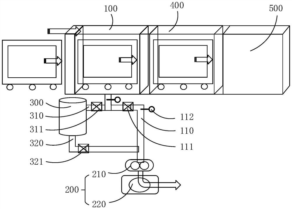
The invention relates to vacuum coating equipment and method. The vacuum coating equipment comprises a buffer chamber, an air extractor and a buffer barrel, the buffer chamber is configured to be used for carrying out buffer treatment on a to-be-coated product before coating, the buffer chamber is provided with an air extraction channel, and the air extraction channel is provided with a first switch valve; the air extractor is arranged at the tail end of the air exhaust channel so as to vacuumize the buffer chamber; the buffer barrel is provided with an air inlet channel and an air outlet channel; the end, away from the buffering barrel, of the air inlet channel is connected between the first switch valve and the buffering chamber in a sealed mode; the end, away from the buffering barrel, of the air outlet channel is connected between the first switch valve and the air extractor in a sealed mode; and the air inlet channel is provided with a second switch valve, and the air outlet channel is provided with a third switch valve. The vacuum coating equipment can solve the problems that the equipment purchase cost is increased and the equipment operation energy consumption is increased due to the mode of reducing the takt time at present.

Description

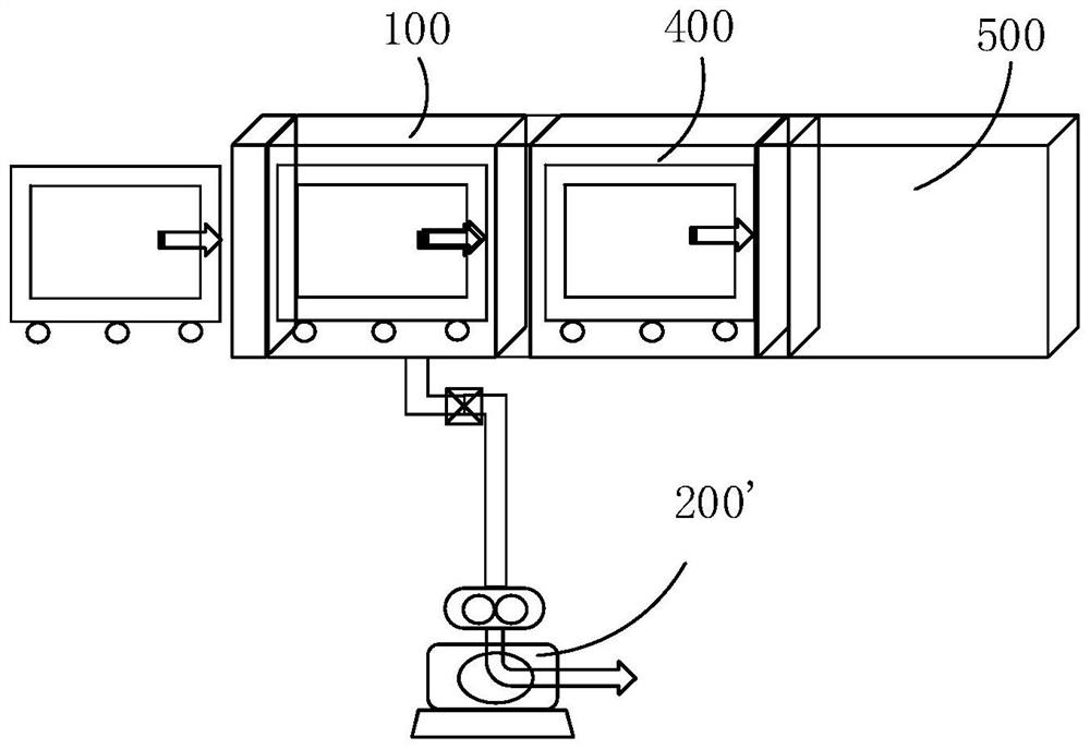
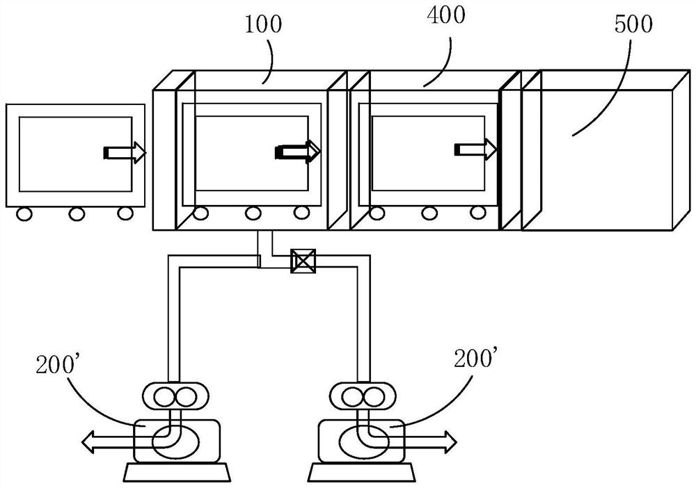
technical field [0001] The invention relates to the technical field of vacuum coating, in particular to vacuum coating equipment and methods. Background technique [0002] In the production industry of display panels, cover panels, solar panels and other panels, vacuum coating devices are needed. In the process of vacuum coating, before the coated products enter the coating chamber for coating, they need to be sent to the buffer room, Transition chamber etc. for vacuum pretreatment or buffer treatment. One of the bottlenecks related to production capacity is the pumping time. Under this background, for the purpose of increasing production, the most direct design of vacuum coating devices currently on the market is to increase the number of pumps to reduce pumping time. In this way, the pumping rate can be improved, the production rhythm can be accelerated, and the production takt time can be reduced. However, increasing the number of air pumps will directly lead to an incr...

Claims


Application Information

Patent Timeline
Patent Type & Authority Applications(China)
IPC IPC(8): C23C14/56
CPCC23C14/566
Inventor 刘清存
Owner INTERFACE TECH CHENGDU CO LTD
Why Eureka
Try Eureka