Automatic chemical copper adding device

An automatic adding and chemical copper technology, which is applied in liquid chemical plating, metal material coating process, coating, etc., can solve the problems that the charging frame cannot be automatically pushed out, the waste of chemical copper resources, and the collection efficiency of chemical copper solution are reduced. , to facilitate collection, improve efficiency and avoid waste

Pending Publication Date: 2021-11-05
COLLEGE OF APPLIED SCI JIANGXI UNIV OF SCI & TECH
View PDF9 Cites 0 Cited by
  • Summary
  • Abstract
  • Description
  • Claims
  • Application Information

AI Technical Summary

Problems solved by technology

[0005] In order to overcome the existing chemical copper automatic adding equipment, adding too much material at one time will easily lead to the waste of chemical copper resources, and the charging frame cannot be automatically pushed out, resulting in a decrease in the collection efficiency of the chemical copper solution. The technical problem of the present invention: provide A chemical copper automatic adding device that can be added quantitatively and can be automatically pushed out for easy collection

Method used


Image

  • Automatic chemical copper adding device
  • Automatic chemical copper adding device
  • Automatic chemical copper adding device

Examples


Embodiment 1

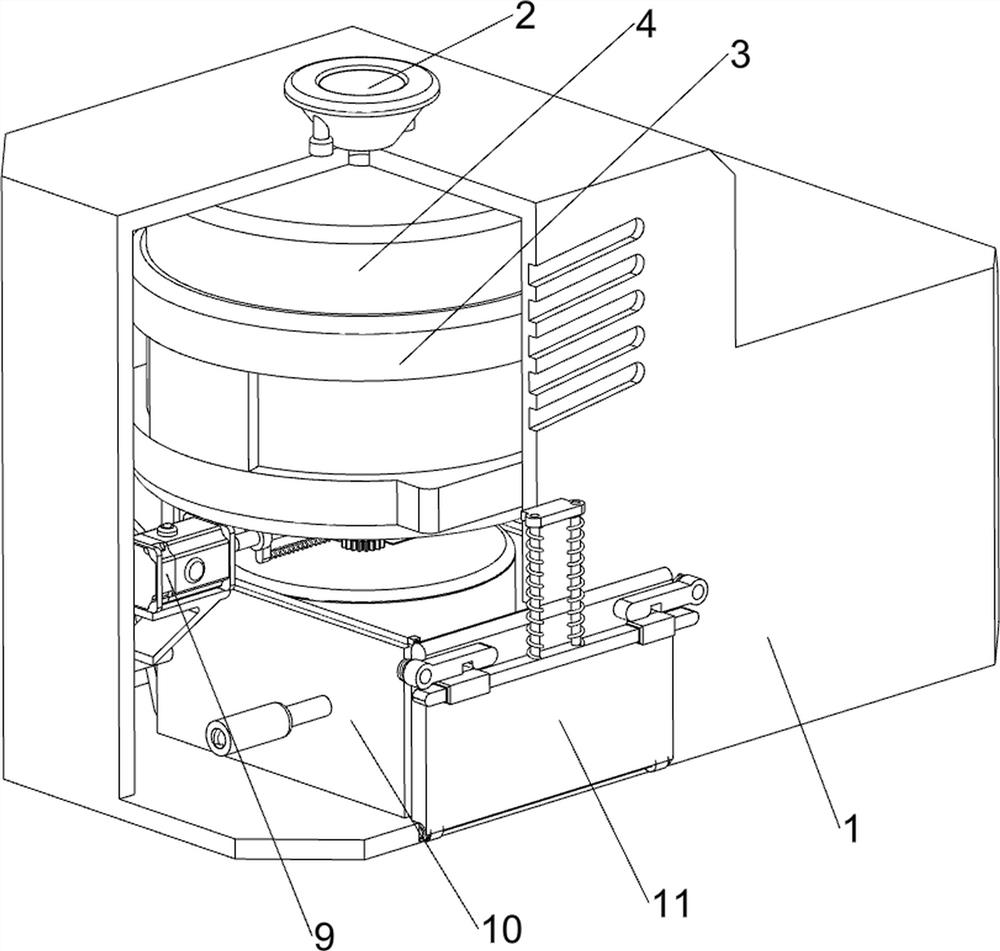
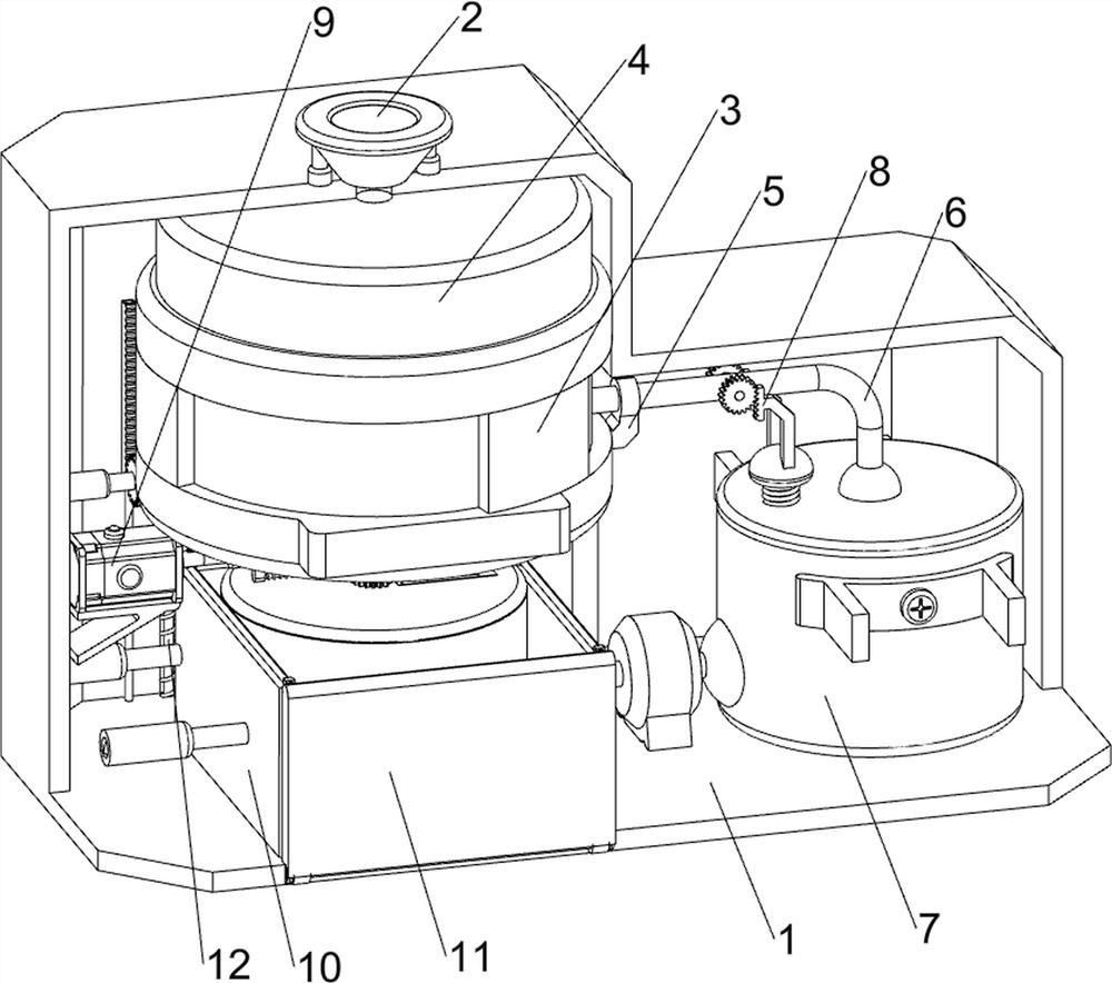
[0037] A chemical copper automatic adding device, such as Figure 1-Figure 8 As shown, it includes a casing 1, a cover 2, a support frame 3, a storage tank 4, a first mounting seat 5, a one-way valve 6, a placement mechanism 7 and a feeding mechanism 8, and a support frame 3 is fixedly connected to the upper left side of the casing 1. A storage tank 4 is installed on the inner side of the support frame 3, a cover 2 is slidably connected between the storage tank 4 and the top left side of the housing 1, a first mounting seat 5 is fixedly connected to the lower right side of the storage tank 4, and a Placement mechanism 7, a one-way valve 6 is connected between the placement mechanism 7 and the storage tank 4, the one-way valve 6 passes through the first installation seat 5, and a feeding mechanism 8 is installed between the placement mechanism 7 and the one-way valve 6.

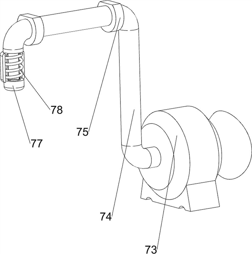
[0038] The placement mechanism 7 includes a bracket 71, a collection tank 72, a filter 73, a conduit 74, a ...

Embodiment 2

[0042] On the basis of Example 1, such as Figure 9-Figure 17 As shown, a stirring assembly 9 is also included, and the stirring assembly 9 includes a servo motor 91, a rotating base 92, a second rotating shaft 93, a bevel gear 94, a third rotating shaft 95 and a stirring rod 96, and the lower left side of the housing 1 is equipped with a servo motor 91, the left side of the bottom of the storage tank 4 is fixedly connected with a swivel seat 92, the inner side of the swivel seat 92 is rotatably provided with a second rotating shaft 93, the second rotating shaft 93 is connected with the output shaft of the servo motor 91, and the inner lower side of the storage tank 4 is rotatably connected There is a third rotating shaft 95, the third rotating shaft 95 and the second rotating shaft 93 are connected with a bevel gear 94, the bevel gears 94 mesh with each other, and the top of the third rotating shaft 95 is connected with a stirring rod 96.

[0043] Also includes a shock assemb...


PUM


Abstract

The invention relates to an adding device, and particularly relates to an automatic chemical copper adding device. The invention aims to provide the automatic chemical copper adding device, and the automatic chemical copper adding device can quantitatively feed materials and can be automatically pushed out to facilitate collection. The automatic chemical copper adding device comprises an outer shell, a supporting frame, a storage tank and a cover, wherein, the supporting frame is arranged on one side of the interior of the outer shell; the storage tank is arranged on the inner side of the supporting frame; and the cover is arranged between the storage tank and one side of the top of the outer shell in a sliding mode. After the solution in a collecting tank is gradually increased, a floating ball is driven to move upwards, and a special-shaped rack reciprocates up and down, so that a ball valve is opened or closed, the quantitative feeding effect is achieved, waste caused by excessive one-time feeding is avoided, when a baffle is opened, a pull rope pulls a sliding plate, the sliding plate pushes a collecting frame forwards, the collecting frame is automatically moved out, the collecting frame does not need to be pulled out manually, collection is convenient, and the solution collecting efficiency of people is improved.

Description

technical field [0001] The invention relates to an adding device, in particular to an automatic chemical copper adding device. Background technique [0002] Electroless copper is an additive used in electroplating, which has the characteristics of fine deposition, high stability, and good bonding force. [0003] In the chemical copper processing and production enterprises, the existing chemical copper automatic adding equipment has a single function, and the operation is too simple, which affects the work efficiency. During the feeding process, adding too much material at one time will easily lead to waste of chemical copper resources, which is difficult The feeding work requires manual stirring of the solution, which increases the labor intensity of people. After the feeding and filtration are completed, the charging frame cannot be automatically pushed out, resulting in a decrease in the collection efficiency of the chemical copper solution. [0004] To sum up, it is nece...

Claims


Application Information

Patent Timeline
Patent Type & Authority Applications(China)
IPC IPC(8): C23C18/16
CPCC23C18/1628
Inventor 魏炳辉
Owner COLLEGE OF APPLIED SCI JIANGXI UNIV OF SCI & TECH
Why Eureka
Try Eureka