Waste copper refining device

A technology for copper refining and adjusting device, applied in descaling device, lighting and heating equipment, furnace components, etc., can solve the problems of complicated operation mode, difficult to control the amount of copper material conveyed, and reduce the working efficiency of scrap copper refining, etc. Enhanced sealing effect

Active Publication Date: 2021-10-01
江西耐乐科技协同创新有限公司 +2
View PDF15 Cites 1 Cited by
  • Summary
  • Abstract
  • Description
  • Claims
  • Application Information

AI Technical Summary

Problems solved by technology

[0003] When refining scrap copper, the scrap copper will be put into the smelting furnace for processing. When transporting copper to the traditional smelting furnace, the operation method is more Complicated and difficult to control the amount of copper conveyed each time, reducing the efficiency of scrap copper refining

Method used


Image

  • Waste copper refining device
  • Waste copper refining device
  • Waste copper refining device

Examples


Embodiment 1

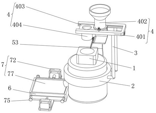
[0030] Example 1, such as Figure 1-8 As shown, the present invention provides a scrap copper refining device, comprising a melting furnace 1 and a regulating device 4, the circular arc surface of the melting furnace 1 is fixedly installed with a fixed ring 2, and the circular arc surface of the fixed ring 2 is evenly fixed with two The supporting rod 3 is provided with an adjustment device 4 at one end of the supporting rod 3 away from the fixing ring 2 .

[0031] Let's talk about the concrete setting and effect of its regulating device 4, auxiliary device 5 and knocking device 7 in detail below.

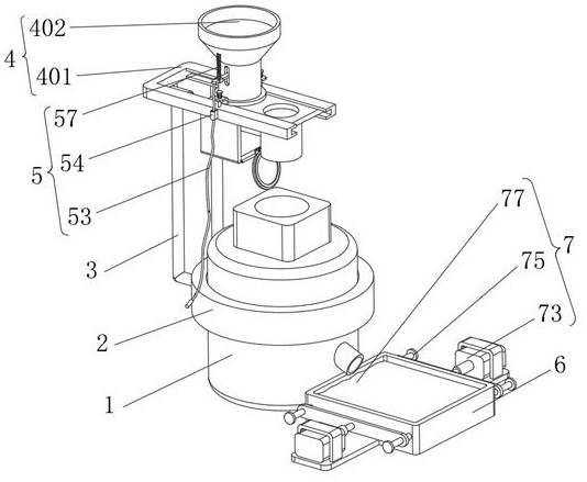
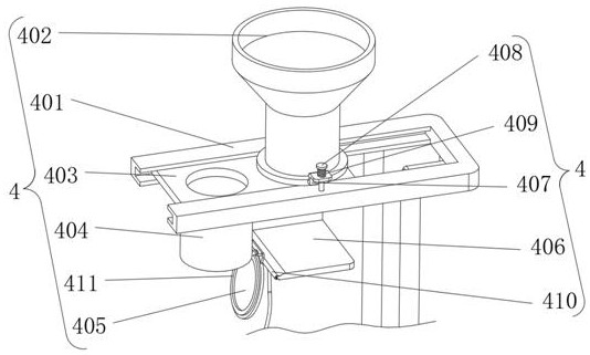
[0032] Such as image 3 and Figure 4As shown, the adjustment device 4 includes a track plate 401, the lower surface of the track plate 401 is fixedly connected with the support rod 3, the track plate 401 is in a "U" shape, and the side of the track plate 401 away from the support bar 3 is clamped with a discharge pipe 402 The inner wall of the track plate 401 is slidably connec...

Embodiment 2

[0038] Embodiment 2, on the basis of embodiment 1, the surface of the feeding pipe 402 is provided with an auxiliary device 5, and the auxiliary device 5 includes a sliding hole 51, and the sliding hole 51 is opened on the surface of the feeding pipe 402, and the inner wall of the sliding hole 51 is rotatably connected There is a rotating plate 52, and the end of the rotating plate 52 away from the inner wall of the slide hole 51 is fixedly connected with a traction rope 53, and the arc surface of the traction rope 53 is slidingly connected with a limit buckle 54, and the surface of the limit buckle 54 is fixedly connected with the track plate 401. The end of the plate 52 away from the traction rope 53 is fixedly connected with a bump 55, the end of the bump 55 away from the rotating plate 52 is pointed, the bumps 55 are evenly distributed on the surface of the rotating plate 52, and the end of the rotating plate 52 close to the pulling rope 53 is slidably connected There is a ...


PUM


Abstract

The invention provides a waste copper refining device and relates to the technical field of waste copper refining equipment. The waste copper refining device comprises a smelting furnace and an adjusting device, a fixing ring is fixedly installed on the arc surface of the smelting furnace, two supporting rods are evenly and fixedly installed on the arc surface of the fixing ring, the adjusting device is arranged at the ends, away from the fixing ring, of the supporting rods, the adjusting device comprises a track plate, the lower surface of the track plate is fixedly connected with the supporting rods, the track plate is in a U shape, a discharging pipe is clamped to the side, away from the supporting rods, of the track plate, the inner wall of the track plate is slidably connected with a rectangular plate, the side, close to a smelting furnace, of the rectangular plate communicates with a material barrel, and the lower end of the material barrel is rotationally connected with a cover plate. According to the device, the problems that when copper materials are conveyed to a traditional smelting furnace, the operation mode is complex, the amount of the copper materials conveyed each time is difficult to control, and the working efficiency of waste copper refining is reduced are solved.

Description

technical field [0001] The invention relates to the technical field of scrap copper refining equipment, in particular to a scrap copper refining device. Background technique [0002] Scrap copper refining refers to a process in which waste copper is put into a smelting furnace for refining. It is widely used in the field of metal manufacturing. Scrap copper has the characteristics of diversity and is finally refined through a variety of processes. [0003] When refining scrap copper, the scrap copper will be uniformly put into the smelting furnace for processing. When transporting copper material to the traditional smelting furnace, the operation method is more complicated, and it is difficult to control the amount of copper material transported each time, reducing the Improve the efficiency of scrap copper refining. Contents of the invention [0004] The object of the present invention is to propose a waste copper refining device in order to solve the shortcomings in the...

Claims


Application Information

Patent Timeline
Patent Type & Authority Applications(China)
IPC IPC(8): F27B14/00F27B14/08F27B14/16F27B14/18F27D25/00C22B15/00C22B7/00
CPCF27B14/00F27B14/08F27B14/0806F27D25/001C22B15/006C22B7/001F27B2014/0812F27B2014/0818Y02P10/20
Inventor 董道伟罗奇梁黄少波雷军肖文云毛玉盛马力安纯亮罗强谭美红
Owner 江西耐乐科技协同创新有限公司
Why Eureka
Try Eureka