
Component for reducing line lateral wind power of straight pole under extreme strong wind

A technology on the side of straight rods and lines, which is applied in the direction of building components, building structures, building types, etc., can solve the problems of shortening the service life of straight rods, poor protection effect of straight rods, economic property losses, etc., and shorten the time for manual disassembly and assembly , Guarantee the effect of stable protection and the effect of guaranteeing stability

Active Publication Date: 2021-11-05
江苏玖泰电力实业有限公司
View PDF6 Cites 0 Cited by
  • Summary
  • Abstract
  • Description
  • Claims
  • Application Information

AI Technical Summary

Problems solved by technology

[0005] In order to solve the above-mentioned technical problems, the present invention provides a line lateral wind force component for reducing linear poles under extremely high winds, so as to solve the problem of poor protection effect on linear poles when the existing wind force components for linear poles are used in extreme windy weather , the linear rod is easily affected by the wind and has a large swing, which may cause cracks at the bottom of the linear rod and shorten the service life of the linear rod, or cause the bottom of the linear rod to break directly, resulting in economic and property losses.

Method used


Image

  • Component for reducing line lateral wind power of straight pole under extreme strong wind
  • Component for reducing line lateral wind power of straight pole under extreme strong wind
  • Component for reducing line lateral wind power of straight pole under extreme strong wind

Examples


Embodiment 1

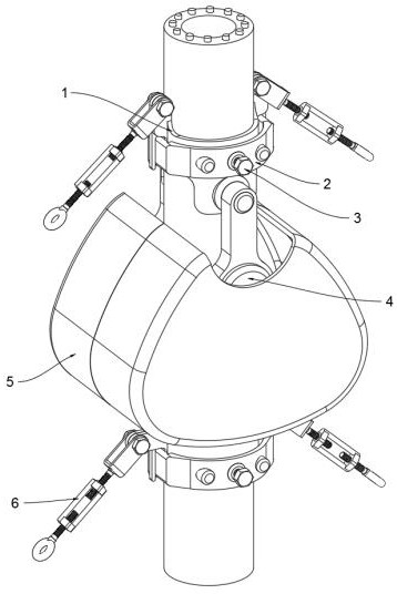
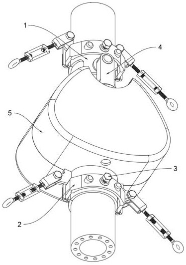
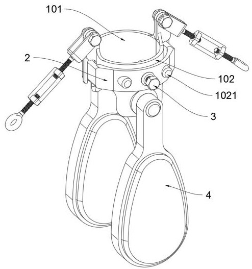
[0032] as attached figure 1 to attach Figure 9 As shown: the present invention provides a line lateral wind force component for reducing linear poles under extremely strong winds, including a fixed collar 1 and a U-shaped clamping piece 2; the fixed collar 1 is connected to the outside of the straight pole, and the fixed collar 1 Both sides are respectively connected with dampers 4; there are two U-shaped clamping parts 2, one of which is connected to the outer side of the fixed collar 1, and the other U-shaped clamping part 2 is connected to the stopper. The outer side of the wind cover 5, and the fastening bolt 3 is connected to the inside of the U-shaped clamping part 2; the windshield cover 5 is fixedly connected to the outside of the straight rod through the U-shaped clamping part 2; 3 is connected with a turnbuckle bolt 6, the top of the turnbuckle bolt 6 is rotatably connected with the fixed collar 1, the two ends of the bottom of the windshield cover 5 are respective...

Embodiment 2

[0037]The fixed hoop 1 includes: a left hoop piece 101 and a right hoop piece 102; the two ends of the left hoop piece 101 are respectively provided with fixed gaps A1011; The two ends of the piece 102 are connected with the two ends of the left hoop piece 101, the outside of the right hoop piece 102 is connected with a U-shaped clamping piece 2, and the two ends of the U-shaped clamping piece 2 are respectively slidably connected in the fixed gap A1011, and the U-shaped clamping There are two guide sliding holes 201 symmetrically inside the part 2, and the guide sliding holes 201 are slidably connected to the outside of the guide column A1021, and the middle part of the U-shaped clamping part 2 is provided with a screw hole 202, and the fastening bolt 3 is threadedly connected to the screw hole 202, and the inner end of the fastening bolt 3 is attached to the outside of the right hoop piece 102; adopting the above-mentioned technical scheme, the U-shaped clamping part 2 on the...

Embodiment 3

[0039] The windshield outer cover 5 includes: a left cover 501 and a right cover 502; the two ends of the left cover 501 are respectively provided with fixed gaps B5011; The two ends of 502 are respectively connected with the two ends of the left cover 501, and the outside of the right cover 502 is connected with a U-shaped clamping piece 2, and the two ends of the U-shaped clamping piece 2 are respectively slidably connected in the fixed gap B5011, and the guide slide hole 201 is slidably connected On the outside of the guide strut B5021, the inner end of the fastening bolt 3 is attached to the outside of the right cover 502; using the above technical solution, the fastening bolt 3 drives the U-shaped clamping part 2 outside the right cover 502 to move horizontally outward, so that The two ends of the U-shaped clamping piece 2 drive the left cover 501 to move horizontally inward, reducing the distance between the left cover 501 and the right cover 502, so that the inside of th...


PUM


Abstract

The invention provides a component for reducing line lateral wind power of a straight pole under extreme strong wind, and relates to the technical field of electric power facilities. The component comprises a fixing hoop and U-shaped clamping pieces, wherein the fixing hoop is connected to the outer side of the straight pole, and dampers are connected to the two sides of the fixing hoop correspondingly; the number of the U-shaped clamping pieces is two, one U-shaped clamping piece is connected to the outer side of the fixing hoop, and the other U-shaped clamping piece is connected to the outer side of a wind shielding outer cover; and fastening bolts are connected inside the U-shaped clamping pieces, and the wind shielding outer cover is fixedly connected to the outer side of the straight pole through the U-shaped clamping pieces. According to the component, when the straight pole shakes under the influence of the line lateral wind power, the dampers on the two sides of the fixing hoop swing synchronously, the shaking amplitude of the straight pole is greatly reduced through self-swing of the dampers, the stability of the straight pole in extreme strong wind weather is guaranteed, the wind-resistant safety level of the straight pole is improved, and therefore, economic property loss caused by breakage of the bottom of the straight pole due to excessive shaking amplitude is avoided.

Description

technical field [0001] The invention belongs to the technical field of electric power facilities, and more specifically relates to a line lateral wind force component for reducing straight poles under extremely high winds. Background technique [0002] Telephone poles are poles for erecting wires. Telephone poles are generally used for lines with low voltage levels. Most of the telegraph poles are made of reinforced concrete. Telegraph poles are widely used in urban and rural power transmission projects. The rod is divided into two types: straight rod and tension rod. The straight rod is used in the straight part of the line and mainly bears the weight of the wire and the side wind force. [0003] Wind power components for straight poles can refer to Patent No. CN110894759A, which mainly includes electric poles, clamping sleeves, connecting cross bars and stable poles. The number of said electric poles is three, and each electric pole is evenly arranged from top to bottom T...

Claims


Application Information

Patent Timeline
Patent Type & Authority Applications(China)
IPC IPC(8): E04H12/00E04H12/20E04B1/92E04B1/98
CPCE04H12/00E04H12/20E04B1/92E04B1/98
Inventor 张宇
Owner 江苏玖泰电力实业有限公司
Learn More