Labyrinth seal for optimizing dynamic characteristics of rotor based on inter-tooth anti-rotation plates

A technology of dynamic characteristics and labyrinth sealing, which is applied in the direction of engine sealing, fluid flow, engine components, etc., and can solve problems such as rotor instability, reduced rotor stability, and insufficient rotor stability

Active Publication Date: 2021-11-05
XI AN JIAOTONG UNIV
View PDF9 Cites 0 Cited by
  • Summary
  • Abstract
  • Description
  • Claims
  • Application Information

AI Technical Summary

Problems solved by technology

However, the labyrinth seal is more likely to cause insufficient rotor stability due to the unsteady airflow excitation force generated by the rotor whirl
Due to the influence of inlet pre-rotation and rotor rotation, the circumferential swirl generated inside the labyrinth seal will greatly promote the tangential airflow excitation force in the same direction as the rotation of the seal cross stiffness, which will lead to rotor instability.
So far, only the sealed inlet anti-rotation plate is used to weaken the circumferential swirl caused by the inlet pre-swirl
When the average circumferential velocity of the inlet airflow is lower than the linear velocity of the rotor, under the viscous drag of the rotor, the circumferential velocity of the airflow will gradually increase along the flow direction, resulting in a decrease in the stability of the rotor.

Method used


Image

  • Labyrinth seal for optimizing dynamic characteristics of rotor based on inter-tooth anti-rotation plates
  • Labyrinth seal for optimizing dynamic characteristics of rotor based on inter-tooth anti-rotation plates
  • Labyrinth seal for optimizing dynamic characteristics of rotor based on inter-tooth anti-rotation plates

Examples


Embodiment Construction

[0027] The implementation of the present invention will be described in detail below in conjunction with the drawings and examples.

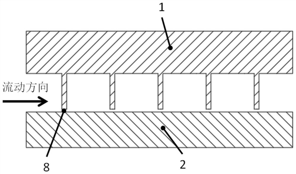
[0028] like figure 1 As shown, a typical straight-through labyrinth seal includes a sealed stator 1 and a sealed rotor 2. The sealing teeth are arranged on the wall of the sealed stator 1. Along the flow direction, there may be multiple sealing teeth, and there is a sealing gap between the sealed rotor 2 and the wall. One 8, the distance of sealing gap one 8 is D 1 .

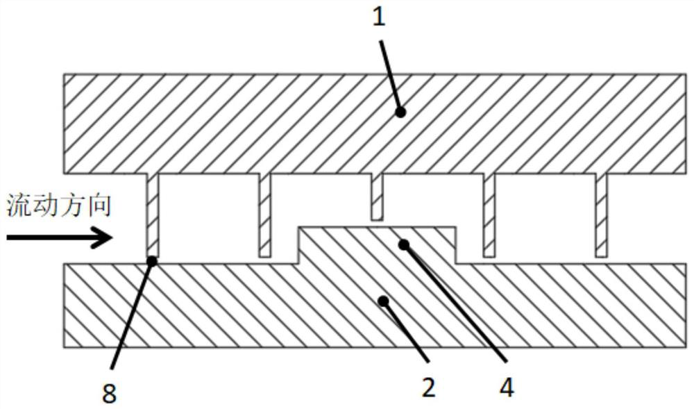
[0029] like figure 2 As shown, a typical labyrinth seal with high and low teeth is based on the straight-through labyrinth seal, and one or more rotor bosses 4 are arranged on the wall of the sealed rotor 2 along the circumferential direction. When the rotor boss 4 is set, all the sealing teeth The length of the seal should be kept consistent with the length of other seal teeth, maintaining a seal gap of 8.

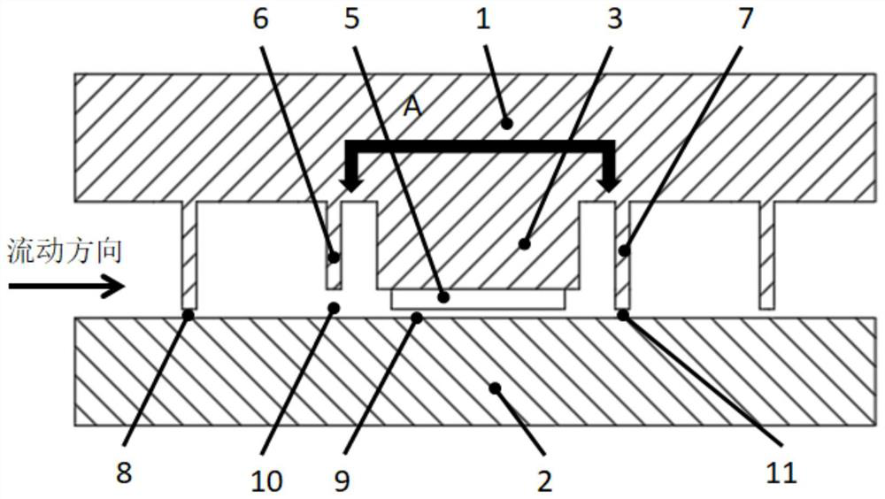
[0030] like image 3 , Figure 4 and Figure 5 , the invention i...


PUM


Abstract

The invention discloses a labyrinth seal for optimizing the dynamic characteristics of a rotor based on inter-tooth anti-rotation plates. The labyrinth seal comprises a sealing stator and a sealing rotor, and a plurality of groups of anti-rotation plate structures are arranged on the wall surface of the sealing stator and located between sealing teeth. Each group of anti-rotation plate structures are evenly distributed in a circumferential direction and deflect in a reverse rotation direction on the meridian plane, so that an airflow can flow to the downstream in the reverse rotation direction through flow guiding of the anti-rotation plate structures. Meanwhile, sealing gaps of upstream sealing teeth and/or downstream sealing teeth adjacent to the anti-rotation plate structures can be changed, so that a radial height of an inter-tooth jet flow is increased. A circumferential rotational flow generated by inlet pre-rotation and rotor rotation in the seal has a great promotion effect on tangential airflow exciting force generated by cross stiffness in a same direction as rotation, and rotor instability can be caused. The labyrinth seal disclosed by the invention can achieve the purposes of weakening the circumferential rotational flow in a sealing cavity, weakening the cross stiffness and enhancing the sealing stability and can well meet the dynamic characteristic requirement of the labyrinth seal rotor so as to improve the turbine operation stability.

Description

technical field [0001] The invention belongs to the technical field of impeller machinery, and in particular relates to a labyrinth seal which optimizes the dynamic characteristics of a rotor based on an anti-rotation plate between teeth. Background technique [0002] The labyrinth seal is a structure installed between the rotor and the stator in the turbomachinery to control the leakage under the high pressure difference. Labyrinth seals are widely used in turbomachinery due to their advantages such as simple structure, low manufacturing cost, and easy maintenance and replacement. However, the labyrinth seal is more likely to cause insufficient rotor stability due to the unsteady airflow excitation force generated by the rotor whirl. Due to the influence of inlet pre-rotation and rotor rotation, the circumferential swirl generated inside the labyrinth seal greatly promotes the cross stiffness of the seal to generate a tangential airflow excitation force in the same directi...

Claims


Application Information

Patent Timeline
Patent Type & Authority Applications(China)
IPC IPC(8): F16J15/447F15D1/02
CPCF16J15/447F15D1/02F15D1/0005Y02E10/20
Inventor 李军薛文松李志刚方志
Owner XI AN JIAOTONG UNIV
Why Eureka
Try Eureka