Method for mfg. hydraulic bearing device

A bearing device, hydraulic technology, applied in the direction of bearings, bearing components, shafts and bearings, etc., can solve the problems of reduced quality of axial components, deviation of axial components from roundness, etc.

Inactive Publication Date: 2003-10-29
NTN CORP
View PDF0 Cites 0 Cited by
  • Summary
  • Abstract
  • Description
  • Claims
  • Application Information

AI Technical Summary

Problems solved by technology

As a result, the quality of the axial member may decrease because the peripheral surface of the axial portion of the ax

Method used


Image

  • Method for mfg. hydraulic bearing device
  • Method for mfg. hydraulic bearing device
  • Method for mfg. hydraulic bearing device

Examples


Embodiment Construction

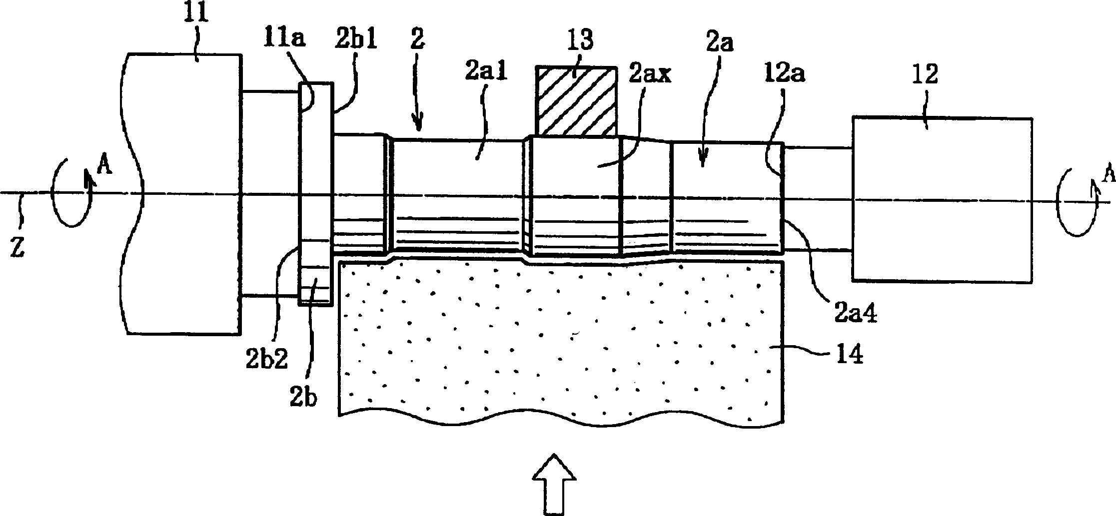
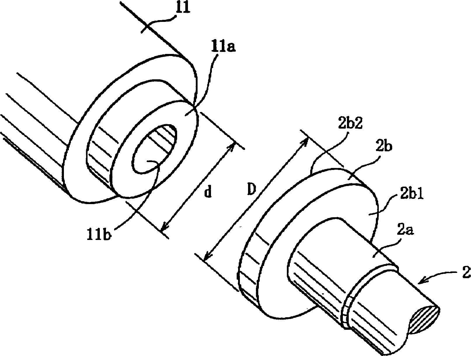
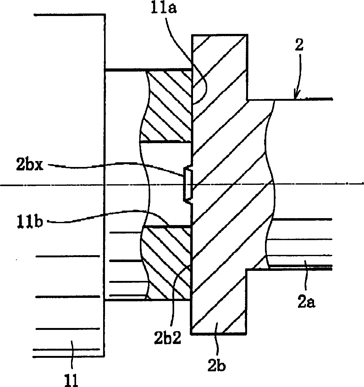
[0033] Hereinafter, preferred embodiments of the present invention will be described with reference to the accompanying drawings. Figure 1-6 is a schematic view showing a state in which a sliding step is performed in the method of manufacturing a hydrodynamic bearing device according to the present invention. Figure 8 is an enlarged sectional front view showing the internal structure of the hydrodynamic bearing device.

[0034] First, for convenience of explanation, the structure of a hydrodynamic bearing device will be described in detail before explaining the state in which the grinding step is performed in the manufacturing method.

[0035] Such as Figure 8 As shown, the hydrodynamic bearing device 1 mainly includes a closed cylindrical shell 7 having an opening 7a at its end, a cylindrical bearing sleeve 8 fixed around the inside of the shell 7, and a cylindrical bearing sleeve 8 mounted on the bearing sleeve 8 The axial member 2 on the inner periphery of the housing ...


PUM


Abstract

Methods for making hydrodynamic bearing devices are provided. The method can effectively increase the peripheral speed when grinding the axial element which is the structural element of the hydrodynamic bearing device, and can prevent centrifugal rotation to improve grinding efficiency and work efficiency, and improve product quality at the same time. An axial member serving as a structural member of a hydrodynamic bearing device is supported at both ends in surface contact using a pair of plate members while rotating the axial member about its axis. The peripheral surface of the axial portion of the axial member is ground on a grinding stone while supporting the peripheral surface of the axial portion with a supporting member. Furthermore, the plate member which is in surface contact with the flange portion of the axial member is formed with at least one turned-out portion in a predetermined area of ​​the center of rotation of the contact surface thereof. In addition, the contact portion of the plate member with the flange portion is elastically supported by an elastic member.

Description

technical field [0001] The invention relates to a method for making a hydrodynamic bearing device. In particular, the present invention relates to a method for making a hydrodynamic bearing device for mounting on an information technology device, such as a magnetic disk device (such as HDD or FDD), an optical disk device (such as CD-ROM, CD- R / RW, or DVD-ROM / RAM), and spindle motors in optical disc devices (such as MD or MO), for scanning motors incorporated in copiers, laser printers (LBP), barcode readers, etc., or Small-sized motors used in electrical equipment such as axial fans. Background technique [0002] It is generally known in the prior art that each of the motors listed above has been proposed to obtain not only high rotational accuracy, but also high rotational speed, low noise, etc., at relatively low cost. As a factor defining these required properties, the bearing support shaft of electric motors is gaining more and more attention. Therefore, in recent yea...

Claims


Application Information

Patent Timeline
IPC IPC(8): B24B5/04B24B41/06F16C17/10F16C33/14
CPCB24B5/04B24B41/065Y10T82/2593Y10T29/49645Y10T29/49639F16C33/14
Inventor 皆见章行平野秀和圆井则雅国分邦玄
Owner NTN CORP
Why Eureka
Try Eureka