Sliding type zoom lens support and lamp structure

A zoom lens and sliding bracket technology, which is applied in the direction of lighting devices, light sources, and light source fixation, can solve the problems of inapplicability, complex structure of rotating and zooming, etc., and achieve the effect of reducing requirements

Pending Publication Date: 2021-11-05
CHENGDU HERCULUX OPTOELECTRONICS TECH CO LTD
View PDF0 Cites 0 Cited by
  • Summary
  • Abstract
  • Description
  • Claims
  • Application Information

AI Technical Summary

Problems solved by technology

The rotary zoom structure is relatively complicated, and some lamps are not suitable for installing rotary structural parts at present, so it is necessary to design a sliding zoom lens bracket

Method used


Image

  • Sliding type zoom lens support and lamp structure
  • Sliding type zoom lens support and lamp structure
  • Sliding type zoom lens support and lamp structure

Examples


Embodiment 1

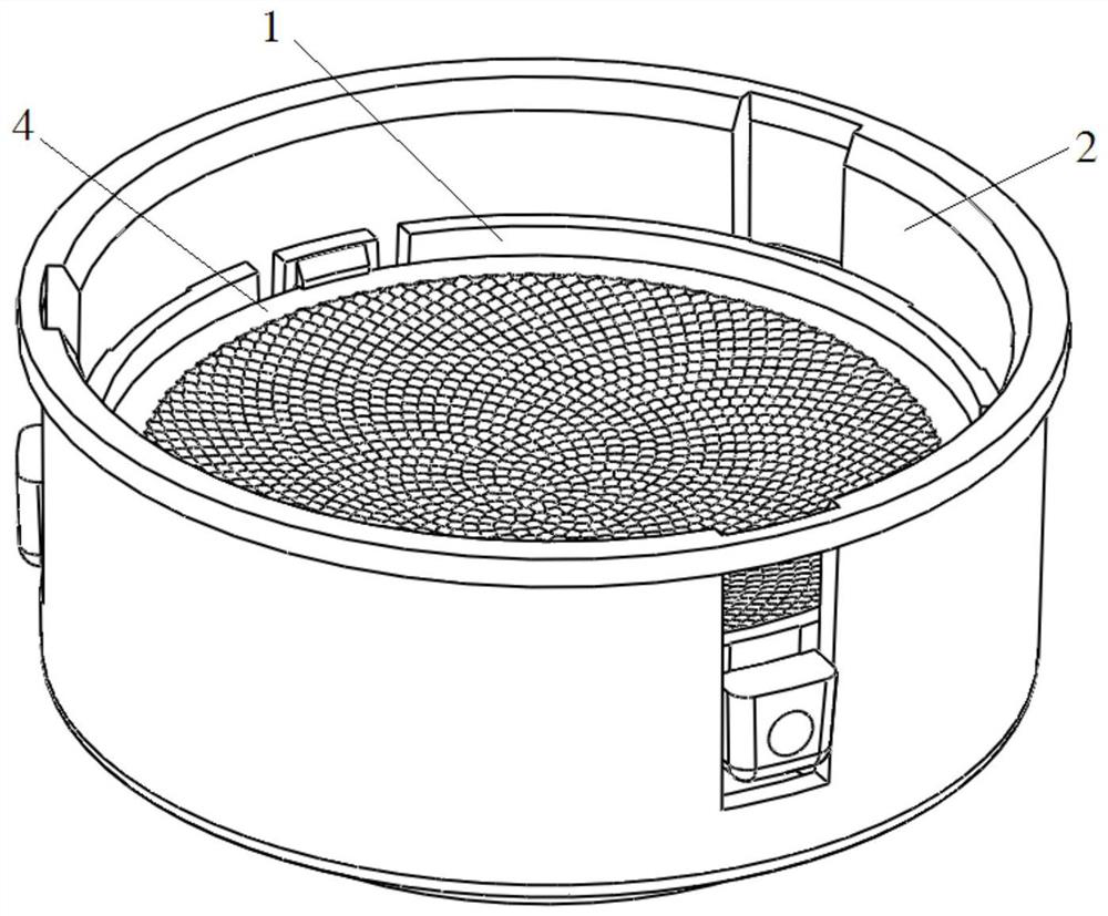
[0033] Such as Figure 4 As shown, a sliding zoom lens bracket includes a sliding bracket 1 and a fixed bracket 2 that are mated and connected to each other. The sliding bracket 1 can slide up and down along the fixed bracket 2 .

[0034] Such as Figure 5 As shown, the sliding bracket 1 is a ring structure, including a main ring body 11, the upper part of the main ring body 11 is provided with an upper buckle 12, and the inner wall of the main ring body 11 is provided with a step 14, the upper buckle 12 and the step 14 It is used to fix the lens 4.

[0035] The lower part of the main ring body 11 is provided with a lower buckle 13, the lower buckle 13 is a PC plastic part, an ABS plastic part, a nylon part or an aluminum part, and the thickness of the lower buckle 13 is 0.5mm-1.5mm, preferably about 1mm. The lower buckle 13 has a certain degree of elasticity, thereby reducing the requirements for the processing technology of the bracket.

[0036] The outer wall of the main...

Embodiment 2

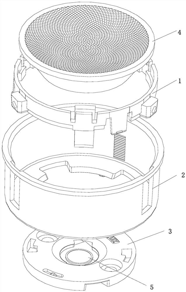
[0043]A lamp structure, including a sliding zoom lens bracket according to Embodiment 1. The sliding bracket 1 is fixedly connected with a lens 4 , and the fixed bracket 2 is fixedly connected with an LED light source 5 . Specifically, such as figure 1 , image 3 As shown, in this embodiment, the lens 4 is a TIR lens, the lens 4 is fixed on the sliding bracket 1 through the upper buckle 12 and the step 14, the LED light source 5 is installed on the light source bracket 3, and the light source bracket 3 and the fixed bracket 2 are fixed through the buckle 26 Connect with the positioning post 27 turnbuckles.

Embodiment 3

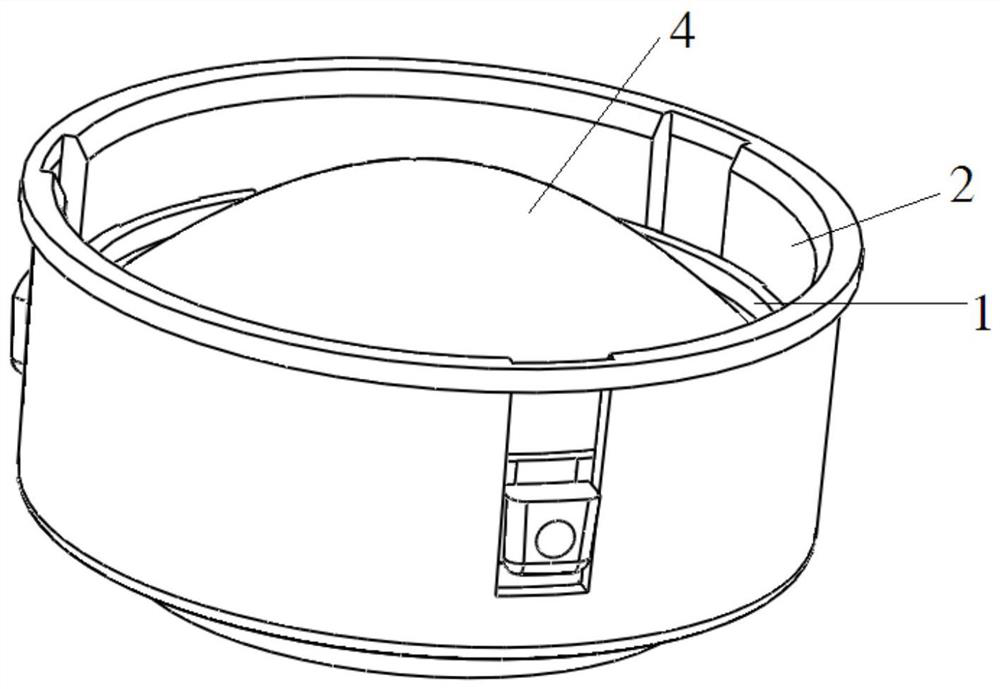
[0045] The difference between this embodiment and embodiment 2 is that, as figure 2 As shown, in this embodiment, the lens 4 is a convex lens.


PUM


Abstract

The invention discloses a sliding type zoom lens support and a lamp structure, the lens support comprises a sliding support and a fixed support which are matched and connected with each other, the sliding support is provided with an upper buckle and a lower buckle, the side wall of the fixed support is provided with a tooth groove, the tooth groove comprises a plurality of racks arranged at intervals, the upper buckle is used for fixing a lens, and the lower buckle can slide up and down along the tooth groove. Through the sliding support and the fixed support which are matched and connected with each other, the sliding support can slide up and down along the fixed support, so that the lens is driven to move, the distance between the lens and the LED light source is adjusted, zooming is achieved, and the lens can be suitable for a lamp requiring sliding zooming; the tooth groove structure is arranged on the fixing support, the distance between the racks determines the minimum distance for focusing variation, the distance between the teeth is set according to the focusing requirement, the distance between the lens and the LED light source can be adjusted conveniently, the tooth height can achieve sliding of the lower buckle with damping feeling in the tooth groove, the tooth height determines the damping feeling, and the good focusing hand feeling can be achieved.

Description

technical field [0001] The invention relates to the technical field of LED lamp lighting, in particular to a sliding zoom lens bracket and a lamp structure. Background technique [0002] At present, the common zoom lens bracket is a rotating zoom structure, and the focal length is adjusted by using a rotating screw mechanism. Correspondingly, a rotating structural part is installed on the lamp. The rotary zoom structure is relatively complicated, and some lamps are not suitable for installing rotary structural parts at present, so it is necessary to design a sliding zoom lens bracket. Contents of the invention [0003] The purpose of the present invention is to provide a sliding zoom lens bracket and a lamp structure in view of the problems existing in the prior art, which can drive the lens to move through the sliding bracket, and then adjust the distance between the lens and the LED light source to realize zooming. [0004] In order to achieve the above object, the tech...

Claims


Application Information

Patent Timeline
Patent Type & Authority Applications(China)
IPC IPC(8): F21K9/20F21K9/69F21V5/04F21V14/06F21V17/02F21V17/16F21Y115/10
CPCF21K9/20F21K9/69F21V5/04F21V14/06F21V17/02F21V17/164F21Y2115/10
Inventor 霍永峰陈益
Owner CHENGDU HERCULUX OPTOELECTRONICS TECH CO LTD
Why Eureka
Try Eureka