
Indicator diagram sensor structure

A sensor and sensor body technology, applied in the field of power map sensor, can solve the problems of inability to conveniently and accurately measure the load of oil extraction machine, power map data, inconvenient maintenance and replacement of power map sensor components, inconvenient battery replacement, etc., so as to avoid the decline of measurement accuracy , Installation and removal are convenient and fast, and the effect of improving test accuracy

Pending Publication Date: 2021-11-05
上海朝辉压力仪器有限公司
View PDF0 Cites 0 Cited by
  • Summary
  • Abstract
  • Description
  • Claims
  • Application Information

AI Technical Summary

Problems solved by technology

[0003] The traditional power map sensor is inconvenient in testing the power map, and it cannot measure the load and power map data of the oil extraction machine more conveniently and accurately, and it is not convenient to repair and replace components of the power map sensor during daily use, and it is also not easy to replace Battery

Method used


Image

  • Indicator diagram sensor structure
  • Indicator diagram sensor structure
  • Indicator diagram sensor structure

Examples


Embodiment Construction

[0023] The following will clearly and completely describe the technical solutions in the embodiments of the present invention with reference to the accompanying drawings in the embodiments of the present invention. Obviously, the described embodiments are only some, not all, embodiments of the present invention. The specific embodiments described here are only used to explain the present invention, not to limit the present invention. Based on the embodiments of the present invention, all other embodiments obtained by persons of ordinary skill in the art without making creative efforts belong to the protection scope of the present invention.

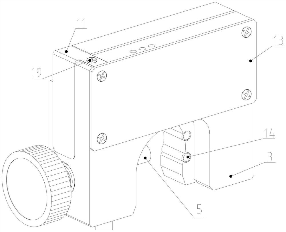
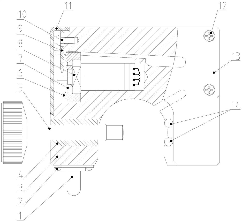
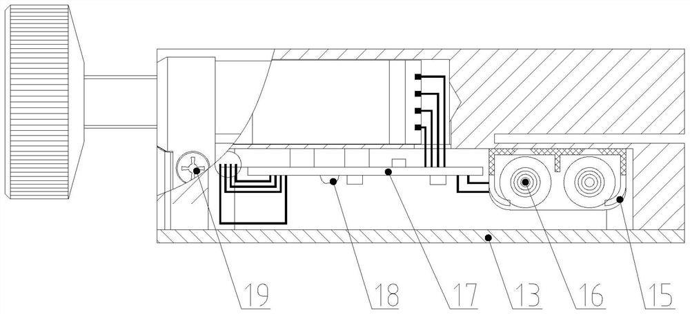
[0024] The present invention provides such Figure 1-3 The shown power sensor structure includes a sensor body 3, and an adjustment assembly is installed inside the bottom end of the sensor body 3. The adjustment assembly includes an adjustment bolt 5, a nut bushing 4 and a pin shaft 14, and the inner side of the sensor body 3 is locked b...


PUM


Abstract

The invention discloses an indicator diagram sensor structure which comprises a sensor body, an adjusting assembly is installed in the bottom end of the sensor body, a force measuring sensor core body is installed in one side of the top end of the sensor body, and the force measuring sensor core body is detachably installed in one side of the top end of the sensor body through a limiting mechanism. The limiting mechanism comprises a sensor installation groove, an installation assembly, a wire hole, a pressing plate and a third cross-shaped groove pan head screw, the sensor installation groove is formed in the sensor body, a force measurement sensor core body is installed in the sensor installation groove, the force measurement sensor core body is installed in the sensor installation groove through the installation assembly, force is laterally applied to the sensor through the pressing plate, so that the stress rod generates displacement change, the displacement change is transmitted to the interior of the sensor core body, and an output signal of the sensor is changed along with the change, thereby achieving the purpose of measurement.

Description

technical field [0001] The invention belongs to the technical field of power map sensors, and in particular relates to the structure of power map sensors. Background technique [0002] The work diagram sensor can also be called the polished rod micro-deformation sensor, which is a device for measuring the load, displacement and work diagram of the pull rod of the oil pumping unit when it is working. The micro-deformation of the tie rod is used to calculate the force load of the tie rod, and at the same time, the stroke of the tie rod is indirectly measured by measuring the acceleration of the tie rod when it is working through the internal high-precision acceleration sensor. [0003] The traditional power map sensor is inconvenient in testing the power map, and it cannot measure the load and power map data of the oil extraction machine more conveniently and accurately, and it is not convenient to repair and replace components of the power map sensor during daily use, and it ...

Claims


Application Information

Patent Timeline
Patent Type & Authority Applications(China)
IPC IPC(8): G01L1/00
CPCG01L1/005
Inventor 伍正辉张笑陈明
Owner 上海朝辉压力仪器有限公司
Learn More