Electric energy meter mounting base and electric meter box

An electric energy meter installation and electric energy meter technology, applied in the direction of measuring devices, measuring electrical variables, instruments, etc., can solve the problems of lack of insulation packaging measures, open current loop, high risk factor of live installation and disassembly, and achieve the realization of bare wire head insulation packaging, The effect of reducing screw tightening steps and avoiding the risk of human injury

Pending Publication Date: 2021-11-05
GUANGDONG POWER GRID CO LTD +1
View PDF0 Cites 0 Cited by
  • Summary
  • Abstract
  • Description
  • Claims
  • Application Information

AI Technical Summary

Problems solved by technology

[0004] There are three main reasons for the low efficiency of the replacement of the electric energy meter. First, the material performance of the secondary voltage and current wires of the electric energy meter is soft, and the efficiency of the wiring fastening method is low.
In the current business scenario, the secondary wiring of the electric energy meter adopts a single-layer insulation single-core 2.5mm 2 Copper wire with single layer insulation single core 4mm 2 Copper wire, the wire core material is soft, and the wiring method is to directly strip off the exposed wire end and connect it to the secondary terminal of the electric energy meter, and then fasten it with screws. Every time the electric energy meter is replaced, it needs to be assembled and disassembled repeatedly
Secondly, the wiring wiring lacks fixing devices, which is prone to wrong wiring problems
In the current business scenario, the wiring of the three-phase metering components of the electric energy meter is distinguished by insulating layers of three colors: yellow, green, and red. However, the identification of the voltage and current lines of the same metering component is not clear, and a meter installer is required. High attention to core 2.5mm 2 with 4mm 2 The difference in wire diameter is to verify the voltage and current lines, which can easily lead to the occurrence of wrong wiring, resulting in the consequences of short circuit of the voltage loop and open circuit of the current loop.
Finally, the voltage and current exposed wire ends lack insulation packaging measures when replacing the energy meter
In the current business scenario, when the energy meter is replaced, it is necessary to use insulating tape to seal the exposed wires of the voltage and current. The operation process is cumbersome, and it is easy to accidentally touch the wires, which will lead to the risk of short circuit of the voltage circuit and open circuit of the current circuit; and the risk factor of live assembly and disassembly High, the insulation packaging measures are delicate and complicated, which is not conducive to the actual business work of the power production department

Method used


Image

  • Electric energy meter mounting base and electric meter box
  • Electric energy meter mounting base and electric meter box
  • Electric energy meter mounting base and electric meter box

Examples


Embodiment 1

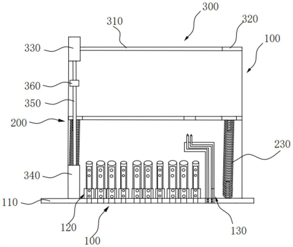
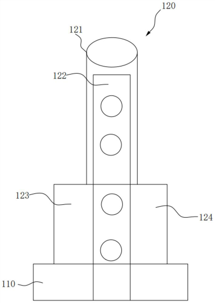
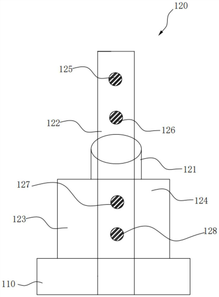
[0035] figure 1 It shows the structure diagram of the electric energy meter installation base and the electric meter box provided by the first embodiment of the present invention, figure 2 A schematic diagram of an unconnected secondary wiring fixing device provided by Embodiment 1 of the present invention is shown, image 3 A schematic diagram of the secondary wiring fixing device after wiring provided by Embodiment 1 of the present invention is shown.

[0036] refer to Figure 1-Figure 3 , The electric energy meter installation base 100 provided in this embodiment includes a bottom plate 110, a plurality of secondary wiring fixing devices 120, a communication wiring device 130, an electric energy meter accommodating device 200 and two supporting plates. A plurality of secondary wiring fixing devices 120 , a communication wiring device 130 and two support plates are vertically fixed on the base plate 110 , and the electric energy meter accommodating device 200 is elastical...

Embodiment 2

[0054] The second embodiment differs from the first embodiment only in that the communication wiring device 130 is different. Figure 7 It shows the schematic diagram of the communication wiring device provided by the second embodiment of the present invention, refer to Figure 7 , The communication wiring device 130 includes an insulating pointer sheath 131 , a pointer 132 , a communication terminal 133 and a pointer spring 134 . The pointer spring 134 is set outside the pointer 132, and the insulating pointer sheath 131 is sheathed outside the pointer spring 134 and the pointer 132. superior. The communication connection terminal of the electric energy meter is located in the communication connection port of the electric energy meter casing. The diameter of the communication connection port of the electric energy meter casing is larger than the diameter of the pointer 132 and smaller than the diameter of the insulating pointer sheath 131. When the pointer 132 is facing the ...


PUM


Abstract

The invention belongs to the technical field of electric energy meter mounting, and discloses an electric energy meter mounting base and an electric meter box. The electric energy meter mounting base comprises a bottom plate and a plurality of secondary wiring fixing devices fixedly connected to the bottom plate, the plurality of secondary wiring fixing devices are in one-to-one correspondence with a plurality of wiring terminals of an electric energy meter to be mounted at equal intervals, and each secondary wiring fixing device comprises an elastic insulating sheath, a conductive block and an insulating fixing block, the conductive block is partially arranged in the insulation fixing block in a penetrating manner, the elastic insulation sheath is arranged outside the conductive block in a sleeving manner and is fixedly connected to the insulation fixing block, the conductive block and the insulation fixing block are respectively and fixedly connected to the bottom plate, and the elastic insulation sheath can be compressed along the installation direction of the secondary wiring fixing device. Efficient and safe replacement of the electric energy meter is achieved, and meanwhile damage to the electric energy meter caused by wrong wiring is effectively avoided.

Description

technical field [0001] The invention relates to the technical field of electric energy meter installation, in particular to an electric energy meter installation base and an electric meter box. Background technique [0002] Smart meters are one of the basic devices for smart grid data collection. They undertake the tasks of raw energy data collection, measurement and transmission, and are the basis for information integration, analysis and optimization, and information presentation. In addition to the basic power consumption measurement function of traditional electric energy meters, smart meters also have two-way multi-rate metering functions, user-side control functions, and two-way data communication with multiple data transmission modes in order to adapt to the use of smart grids and new energy. Function, anti-theft function and other intelligent functions. The smart meter is an intelligent instrument with microprocessor application and network communication technology ...

Claims


Application Information

Patent Timeline
IPC IPC(8): G01R11/04
CPCG01R11/04
Inventor 董伟锋蒋敬鹤方绍怀梁永昌
Owner GUANGDONG POWER GRID CO LTD
Why Eureka
Try Eureka