Rainproof, moistureproof and dustproof air duct structure for power distribution cabinet and using method thereof

A technology for power distribution cabinets and air ducts, which is applied in the field of rain-proof, moisture-proof and dust-proof air duct structures for power distribution cabinets, which can solve the problems of poor moisture-proof and dust-proof effects, inability to use desiccant to remove moisture, and inability to install dust- and moisture-removing structures according to requirements and other problems, to achieve the effect of fast installation and use, and good moisture removal effect

Inactive Publication Date: 2021-11-05
李玉常
View PDF1 Cites 1 Cited by
  • Summary
  • Abstract
  • Description
  • Claims
  • Application Information

AI Technical Summary

Problems solved by technology

[0005] In order to solve the above technical problems, the present invention provides a rain-proof, moisture-proof and dust-proof air duct structure for power distribution cabinets and its use method, so as to solve the problem of poor moisture-proof and dust-proof effect when the existing air duct structures for power distribution cabinets are in use. Poor, it is impossible to remove the dust and moisture from the passing wind, and it is impossible to install the dust and moisture removal structure according to the demand, and the existing air duct structure for the power distribution cabinet cannot automatically control the movement of the desiccant after a long period of use, and cannot make the desiccant Make the most of moisture removal issues

Method used


Image

  • Rainproof, moistureproof and dustproof air duct structure for power distribution cabinet and using method thereof
  • Rainproof, moistureproof and dustproof air duct structure for power distribution cabinet and using method thereof
  • Rainproof, moistureproof and dustproof air duct structure for power distribution cabinet and using method thereof

Examples


Embodiment

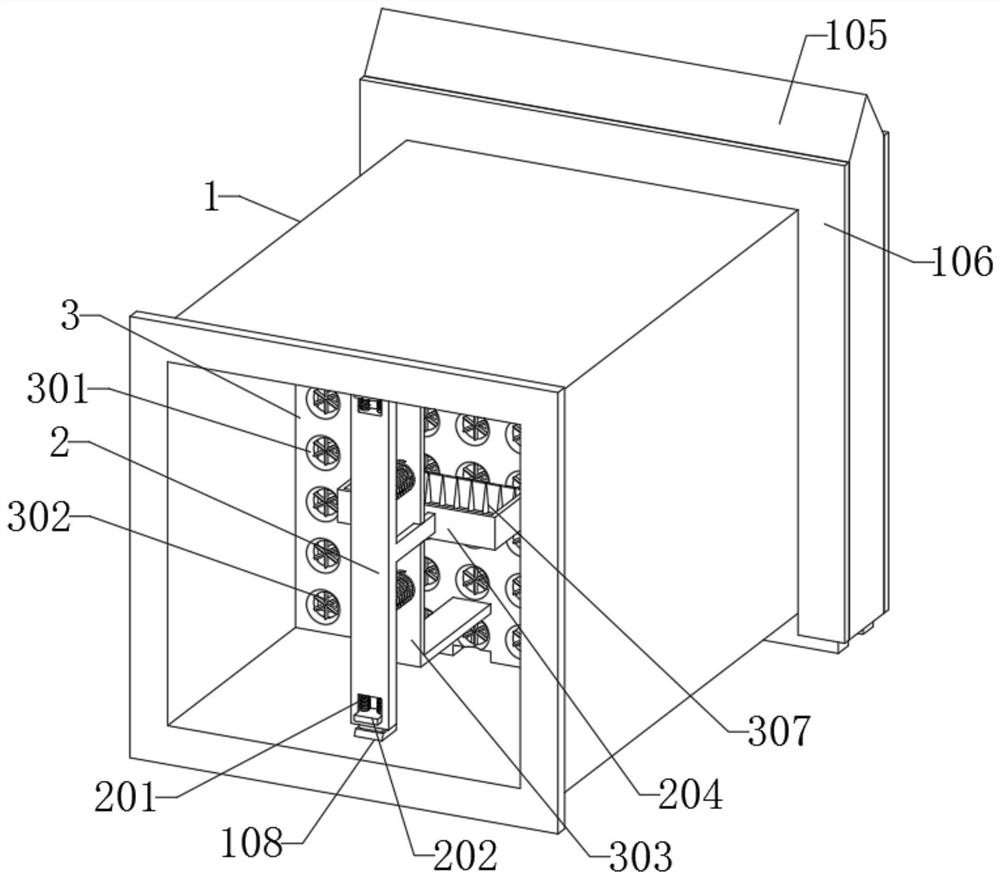
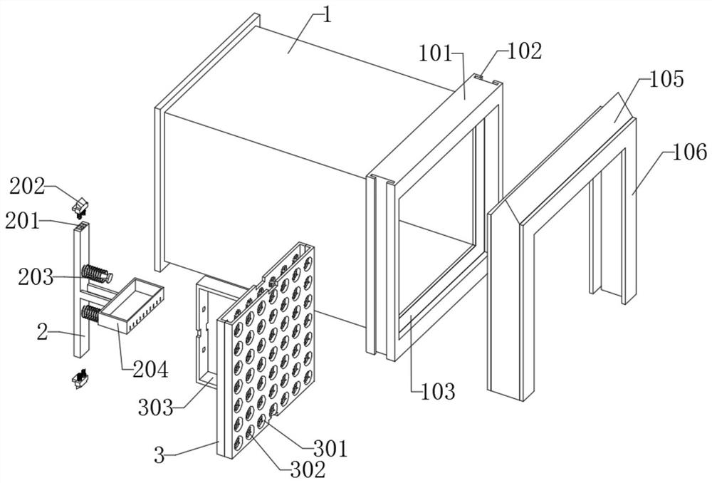
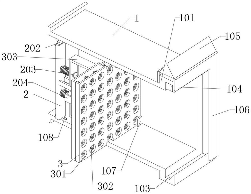
[0033] as attached figure 1 to attach Figure 8 Shown:

[0034]The invention provides a rain-proof, moisture-proof and dust-proof air duct structure for a power distribution cabinet and its use method, including a main body 1; To the inside of the bottom groove 103 of another main body 1, and then after the multiple main bodies 1 are spliced ​​and connected, the sealing effect is better. The rear end of the main body 1 is installed with a push rod 2 inside, and the inner middle of the main body 1 is installed with a mounting plate 3; The ejector rod 2, the ejector rod 2 is a rectangular structure, and the ejector rod 2 is installed in the middle of the rear end of the main body 1; the mounting plate 3, the mounting plate 3 includes a scraping mechanism, and the rear end of the mounting plate 3 is equipped with a scraping mechanism , the mounting plate 3 is a rectangular plate structure, and the interior of the mounting plate 3 is provided with a rectangular groove.

[0035]...


PUM


Abstract

The invention provides a rainproof, moistureproof and dustproof air duct structure for a power distribution cabinet and a using method thereof, relates to the field of air duct structures, and aims to solve the problems that when an existing air duct structure for the power distribution cabinet is used, the moistureproof and dustproof effect is poor, passing air cannot be subjected to dust removal and moisture removal treatment, and a dust removal and moisture removal structure cannot be installed according to needs. The air duct structure comprises a main body. The main body is of a rectangular structure, a rectangular frame is arranged on the outer side of the rear end of the main body, an ejector rod is mounted in the rear end of the main body, and a mounting plate is mounted in the middle of the interior of the main body; and the ejector rod is of a rectangular structure, and the ejector rod is installed in the middle of the interior of the rear end of the main body. The mounting plate can compress the spring on the outer side of the guide rod through the stress plate, so that the scraping plate and the scraping teeth can move in the storage part, the scraping plate can scrape the compact drying agent at the bottom of the storage part, meanwhile, the scraping teeth can divide and disperse the drying agent, the drying agent can be turned up, and then the drying agent can absorb moisture to the maximum extent.

Description

technical field [0001] The invention belongs to the technical field of air duct structure, and more specifically relates to a rain-proof, moisture-proof and dust-proof air duct structure for a power distribution cabinet and a use method thereof. Background technique [0002] When the power distribution cabinet is in use, it is usually necessary to use pipes to ventilate the inside of the power distribution cabinet, so that the heat and air can be quickly discharged. [0003] For example, the application number: CN201811276037.1 relates to a decorative air duct for low-voltage power distribution cabinets, including a power distribution cabinet body and an air duct shell, the air duct shell is fixedly connected to the side panel of the power distribution cabinet body, and the air duct shell and the side panel form a A decorative air channel, the air channel housing includes a housing side panel and end panels arranged at both ends of the housing side panel, the end panels are ...

Claims


Application Information

Patent Timeline
Patent Type & Authority Applications(China)
IPC IPC(8): H02B1/28H02B1/30H02B1/56B01D53/26B01D53/04
CPCH02B1/28H02B1/306H02B1/565B01D53/26B01D53/261B01D53/0407
Inventor 李玉常
Owner 李玉常
Why Eureka
Try Eureka