A large X-ray machine operating table arm support

A technology of an operating bed and an X-ray machine, applied in the field of bed arm rests, can solve problems such as inability to position at any point, and achieve the effects of simple structure, convenient installation and use, and easy production.

Active Publication Date: 2019-01-22
李平 +2
View PDF12 Cites 0 Cited by
  • Summary
  • Abstract
  • Description
  • Claims
  • Application Information

AI Technical Summary

Problems solved by technology

The rotating base is installed on one side of the operating bed, and the base is provided with a horizontally rotating rotating shaft. The rotating shaft is sleeved on the bracket, and the rotating shaft and the bracket are rotated out to the vertical state of the operating bed for puncturing. The working state is to fix a fixed point for operation. , the arm is stretched out or perpendicular to the human body, and two fixing straps need to be set on the arm frame to fix it. It cannot be moved or positioned at any point, and the patient cannot be operated in a natural and relaxed state, which is likely to bring sequelae to the patient.

Method used


Image

  • A large X-ray machine operating table arm support
  • A large X-ray machine operating table arm support
  • A large X-ray machine operating table arm support

Examples


Embodiment 1

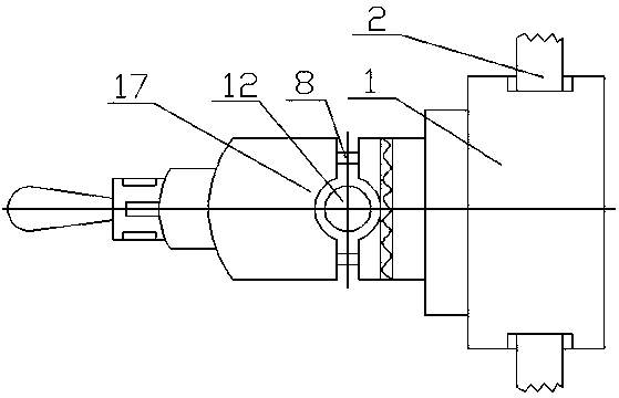
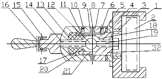
[0046] Embodiment 1, referring to the accompanying drawings, the sliding sleeve buckle opening (26) of the sliding sleeve (1) is sleeved on the rod of the side frame rod (2). The tail core bolt (19) is connected with the tail core bolt hole (25) of the sliding sleeve (1) and the tail core connecting screw hole (31) of the tail core (32). The adjusting head core screw (14) of the adjusting head (34) passes through the head cover connecting hole (29) of the head cover (9) and is connected with the head core connecting screw hole (30) of the head core (13). The outer diameter of the head core (13) and the tail core (32) are sleeved in the inner cavity (28) of the head cover (9) and the middle sleeve (7), and the tail core (32) is installed in the tail core installation port ( 36), and installed in the inner cavity (28) of the middle sleeve (7), the head sleeve bolt (10) is inserted into the adjustment groove (11) through the head sleeve bolt hole (27), and the middle sleeve bolt ...

Embodiment 2

[0047] Example 2, referring to Example 1, referring to the accompanying drawings, the head core (13) and the tail core (32) do not need the transmission connecting groove (20) and the transmission connecting core strip (21), but the head core (13) and the tail core (32) are connected as a whole, and a circular hole is opened in the middle of the head core (13) and the tail core (32) to install the arm support guide rod (12). For other structures, refer to Embodiment 1, and the same effect can be achieved.

Embodiment 3

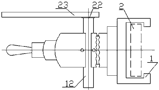
[0048] Example 3, referring to Example 1 or 2, referring to the accompanying drawings, remove the handle (16), head cover (9), middle cover (7), seat cover (4), head core (13), tail core ( 32) and related bolts, and the sliding sleeve (1) is transformed into a ratchet structure, that is, a ratchet structure is installed between the arm support (23) and the side frame rod (2). 23) When it is necessary to run and / or stay locked during use on the side of the operating bed, it can be run and locked with the distance of the stroke.


PUM


Abstract

The invention discloses a large X-ray machine operating table arm support. The arm support is characterized in that a sliding sleeve is sleeved with a lateral rack rod, a base sleeve is fixedly connected with the sliding sleeve through a fixing clamping strip, a middle sleeve meshes with the base sleeve through a tooth combination, a head sleeve is installed at the front end of the middle sleeve, an adjusting head is installed in front of the head sleeve, the head sleeve is connected with a handle, a head core and a tail core are installed in an inner cavity of the head sleeve and in the inner cavity of the middle sleeve respectively, an inner hole is formed in the base sleeve, the outer diameter portion of an arm support guide rod is sleeved with a head core sleeve opening and a tail core sleeve opening, a head core screw is adjusted to be connected with a head core connection screw hole through a head sleeve connection hole, a tail core bolt is in threaded connection with a tail core connection screw hole through the sliding sleeve, a middle sleeve bolt is clamped into an adjusting groove through a middle sleeve bolt hole, a head sleeve bolt is clamped into the adjusting groove through a head sleeve bolt hole, and a handle adjusting bolt is connected with the adjusting head through a handle installation hole. The arm support has the advantages that the structure is simple, manufacturing is easy, materials are easy to find, the cost is low, detachment and installation are quick, installation and use are convenient, the arm support is safe and reliable, pain of patients is reduced, and the comfort of the patients is improved.

Description

technical field [0001] The invention relates to a bed arm support, in particular to an arm support of a large-scale X-ray machine operating bed. Background technique [0002] The bed in the prior art is composed of several bed boards, covered with straw mats or Simmons mattresses, and there is no arm rest installed on the side of the bed. When the patient's arm is turned on the side of the human body, the patient's arm is exposed to the side of the bed, and sometimes the hanging state is unnatural, which brings obstacles to the implementation of arm surgery. question. Comparative document 1, application number: CN200620106840, name of invention: adjustable knee joint fixation support, including an upper fixing frame connected by an upper support steel bar and an upper positioning ring, and a lower support steel bar connected by the lower positioning ring. The fixing frame, the lower end of the upper supporting steel bar is fixedly connected to the angle adjustment piece wi...

Claims


Application Information

Patent Timeline
Patent Type & Authority Patents(China)
IPC IPC(8): A61G13/12A61B6/00
CPCA61B6/00A61G13/101A61G13/1235
Inventor 李平陈容谢文超
Owner 李平
Why Eureka
Try Eureka