
Bendable interventional probe and ultrasonic imaging device

A bending and wire-drawing technology, applied in diagnostic probe accessories, ultrasonic/sonic/infrasonic diagnosis, sound wave diagnosis, etc., can solve problems such as insufficient flexibility and inability to realize bending, and achieve the effect of expanding application scenarios and great flexibility

Pending Publication Date: 2021-11-09
SUZHOU INST OF BIOMEDICAL ENG & TECH CHINESE ACADEMY OF SCI
View PDF0 Cites 0 Cited by
  • Summary
  • Abstract
  • Description
  • Claims
  • Application Information

AI Technical Summary

Problems solved by technology

[0002] In vivo interventional ultrasound imaging mainly uses ultrasonic probes to intervene in the human body to image blood vessels, digestive tract, bronchi, heart and other in vivo tissues. At present, common ultrasonic imaging probes use a flexible shaft to drive the front-end ultrasonic components to rotate for imaging. , such as IVUS, ICE, bronchial ultrasound, digestive ultrasound and other ultrasound probes; the flexible shaft can be rotated, but it cannot be bent, and the flexibility is not enough. Therefore, when entering some irregular cavities or some irregular tissues need to be Existing ultrasound probes face greater difficulties when imaging

Method used


Image

  • Bendable interventional probe and ultrasonic imaging device
  • Bendable interventional probe and ultrasonic imaging device
  • Bendable interventional probe and ultrasonic imaging device

Examples


Embodiment 1

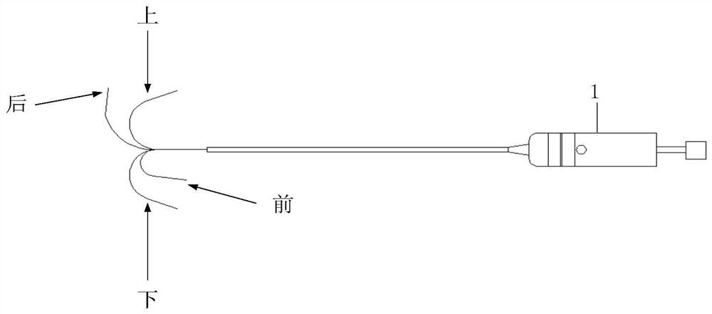
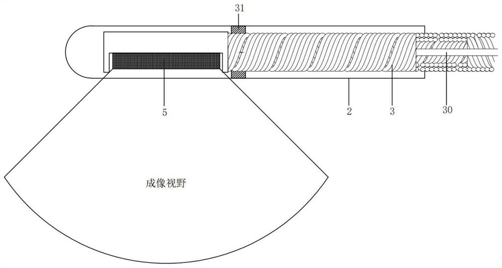
[0049] Such as figure 1 As shown, a bendable interventional probe in this embodiment includes: a housing 1, a sheath 2 connected to the housing 1, a transmission flexible shaft 3 rotatably arranged in the sheath 2, and a transmission flexible shaft 3 for driving A rotating drive mechanism 4, an ultrasonic probe 5 arranged at the front end of the flexible transmission shaft 3, and a bending mechanism 6 for bending the front end of the flexible transmission shaft 3 in the up-down direction and in the front-back direction;

[0050]The bending mechanism 6 includes front and rear rotating wheels 60, front and rear bending drawing wires 61 wound on the front and rear rotating wheels 60, up and down rotating wheels 63, up and down bending drawing wires 64 wound on the up and down rotating wheels 63, and front and rear rotating wheels 60 meshed. The front and rear bending knobs 62 and the up and down bending knobs 65 meshed with the up and down rotating wheels 63, the two movable ends...

Embodiment 2

[0090] refer to Figure 9 , this embodiment provides an ultrasonic imaging device, including the bendable interventional probe of Embodiment 1 and an ultrasonic imaging host 7 connected to the bendable interventional probe.

[0091] The ultrasonic imaging host 7 is connected to the cable 30 drawn out from the slip ring 43 and the cable 30 drawn out from the drive mechanism 4. On the one hand, it can process the ultrasonic signal to generate a three-dimensional ultrasonic image; on the other hand, it can control the bendable interventional probe. .


PUM


Abstract

The invention discloses a bendable interventional probe and an ultrasonic imaging device. The bendable interventional probe comprises a shell, a sheath tube connected with the shell, a transmission flexible shaft rotatably arranged in the sheath tube, a driving mechanism for driving the transmission flexible shaft to rotate, an ultrasonic probe arranged at the front end of the transmission flexible shaft, and a bending mechanism used for bending the front end of the transmission flexible shaft in the up-down direction and the front-back direction. According to the bendable interventional probe provided by the invention, the bendable interventional probe can be bent in the front-back direction and the up-down direction through a manual control method, and the bendable interventional probe has a rotating function and a bending function and is higher in flexibility; and the bendable interventional probe can conveniently enter some irregular cavities for imaging or can realize imaging on more irregular tissue areas, so that the application scene of the ultrasonic probe can be expanded. The bendable interventional probe provided by the invention can be matched with an ultrasonic imaging host, and three-dimensional imaging is realized through three-dimensional rotation of the probe.

Description

technical field [0001] The invention relates to the field of medical ultrasonic equipment, in particular to a bendable interventional probe and an ultrasonic imaging device. Background technique [0002] In vivo interventional ultrasound imaging mainly uses ultrasonic probes to intervene in the human body to image blood vessels, digestive tract, bronchi, heart and other internal tissues. At present, the common ultrasonic imaging probe uses a flexible shaft to drive the front end of the ultrasonic component to rotate for imaging. , such as IVUS, ICE, bronchial ultrasound, digestive ultrasound and other ultrasonic probes; the flexible shaft can be rotated, but it cannot be bent, and the flexibility is not enough. Therefore, when entering some irregular cavities or some irregular tissues need to be When imaging, existing ultrasound probes will face greater difficulties. [0003] Therefore, a more reliable solution is now needed. Contents of the invention [0004] The techni...

Claims


Application Information

Patent Timeline
Patent Type & Authority Applications(China)
IPC IPC(8): A61B8/12
CPCA61B8/12A61B8/4444A61B8/42
Inventor 韩志乐吕加兵朱鑫乐崔崤峣简小华
Owner SUZHOU INST OF BIOMEDICAL ENG & TECH CHINESE ACADEMY OF SCI
Learn More