Traction device for plastic pipe production

A plastic pipe and traction device technology, applied in the direction of transportation and packaging, conveyor objects, rollers, etc., can solve the problems of traction slipping, poor stability, and affecting the production and processing of plastic pipe traction, and achieve increased traction friction and traction. The effect of stable conveying and avoiding traction and offset conveying

Pending Publication Date: 2021-11-09
六安市强盛塑胶有限公司
View PDF0 Cites 0 Cited by
  • Summary
  • Abstract
  • Description
  • Claims
  • Application Information

AI Technical Summary

Problems solved by technology

[0002] As an important part of chemical building materials, plastic pipes are widely accepted by users for their superior performance, hygiene, environmental protection, and low consumption. They mainly include UPVC drainage pipes, UPVC water supply pipes, aluminum-plastic composite pipes, and polyethylene (PE) pipes. Water supply pipes, polypropylene PPR hot water pipes, etc. In the production process of plastic pipes, conveyor belts are used to transport plastic pipes in the prior art. The traction and transportation stability of plastic pipes is poor, and traction slips are prone to occur, which affects plastic pipes. traction production and processing, therefore, we design a traction device for plastic pipe production

Method used


Image

  • Traction device for plastic pipe production
  • Traction device for plastic pipe production
  • Traction device for plastic pipe production

Examples


Embodiment Construction

[0019] The technical solutions in the embodiments of the present invention will be clearly and completely described below in conjunction with the accompanying drawings in the embodiments of the present invention. Obviously, the described embodiments are only some of the embodiments of the present invention, not all of them; based on The embodiments of the present invention and all other embodiments obtained by persons of ordinary skill in the art without creative efforts all belong to the protection scope of the present invention.

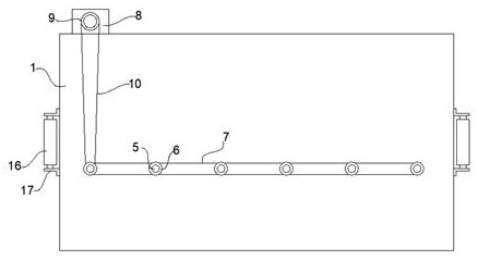
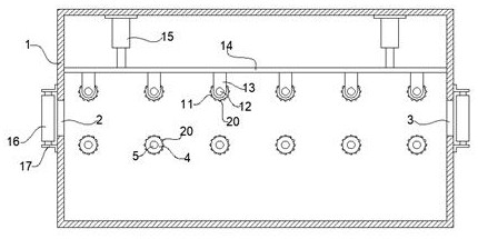
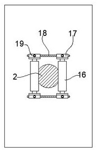
[0020] Such as Figure 1-4 As shown, the present invention discloses a traction device for plastic pipe production, comprising a traction box 1, an inlet 2, and an outlet 3, and the left and right sides of the traction box 1 are symmetrically provided with an inlet 2 and an outlet 3, The bottom of the inner chamber of the traction box 1 is evenly distributed with a plurality of lower traction rollers 4, and the front and rear end surfaces of the lo...


PUM


Abstract

The invention discloses a traction device for plastic pipe production. The traction device for plastic pipe production comprises a traction box body, wherein a plurality of lower traction rollers and upper traction rollers are uniformly distributed in the traction box body, a lower shaft end and an upper shaft end which are of an integrated structure are separately arranged on the front end surface and the rear end surface of each lower traction roller and each upper traction roller, and the lower shaft ends are rotatably connected to the traction box body; double-rack chain wheels are installed on the lower shaft ends in a sleeving mode, the uniformly-distributed double-rack chain wheels are in transmission connection through a chain I, a driving motor is installed on the top wall of the traction box body, a driving chain wheel is installed at the output end of the driving motor in a sleeving mode, and the driving chain wheel is in transmission connection with the double-rack chain wheels through a chain II; and the upper shaft ends are rotationally connected to a lifting lug plate, the lifting lug plate is vertically connected to a lifting plate, the two sides of the top surface of the lifting plate are fixedly connected with telescopic tail ends of hydraulic cylinders separately, and the hydraulic cylinders are installed on the inner top wall of the traction box body in a hanging mode. By the adoption of the technical scheme, the traction device for plastic pipe production is simple in structure, convenient to assemble and install, and stable in traction conveying, and facilitates increasing the traction production efficiency.

Description

technical field [0001] The invention relates to the technical field of plastic pipe production, in particular to a traction device for plastic pipe production. Background technique [0002] As an important part of chemical building materials, plastic pipes are widely accepted by users for their superior performance, hygiene, environmental protection, and low consumption. They mainly include UPVC drainage pipes, UPVC water supply pipes, aluminum-plastic composite pipes, and polyethylene (PE) pipes. Water supply pipes, polypropylene PPR hot water pipes, etc. In the production process of plastic pipes, conveyor belts are used to transport plastic pipes in the prior art. The traction and transportation stability of plastic pipes is poor, and traction slipping is prone to occur, which affects plastic pipes. Therefore, we design a traction device for plastic pipe production. Contents of the invention [0003] In order to solve the defects of the prior art solutions, the inventi...

Claims


Application Information

Patent Timeline
Patent Type & Authority Applications(China)
IPC IPC(8): B29C48/355B29C48/09B65G13/02B65G39/02B65G39/12B65G13/07
Inventor 王娟
Owner 六安市强盛塑胶有限公司
Why Eureka
Try Eureka