Method for estimating precession parameters of middle-section target of ballistic missile

A technology for parameter estimation and ballistic missiles, applied to radio wave measurement systems, instruments, etc., can solve the problem of low recognition ability of true and false targets, and achieve the effect of improving recognition ability

Active Publication Date: 2021-11-09
HARBIN INST OF TECH
View PDF5 Cites 2 Cited by
  • Summary
  • Abstract
  • Description
  • Claims
  • Application Information

AI Technical Summary

Problems solved by technology

[0005] The purpose of the present invention is to solve the problem that the existing precession feature estimation method fails to utilize the micro-movement features of general scattering points such as tail fins, and the existing precession feature estimation method has a low ability to identify true and false targets, and A method for estimating the precession parameters of a ballistic missile mid-course target is proposed

Method used


Image

  • Method for estimating precession parameters of middle-section target of ballistic missile
  • Method for estimating precession parameters of middle-section target of ballistic missile
  • Method for estimating precession parameters of middle-section target of ballistic missile

Examples


specific Embodiment approach 1

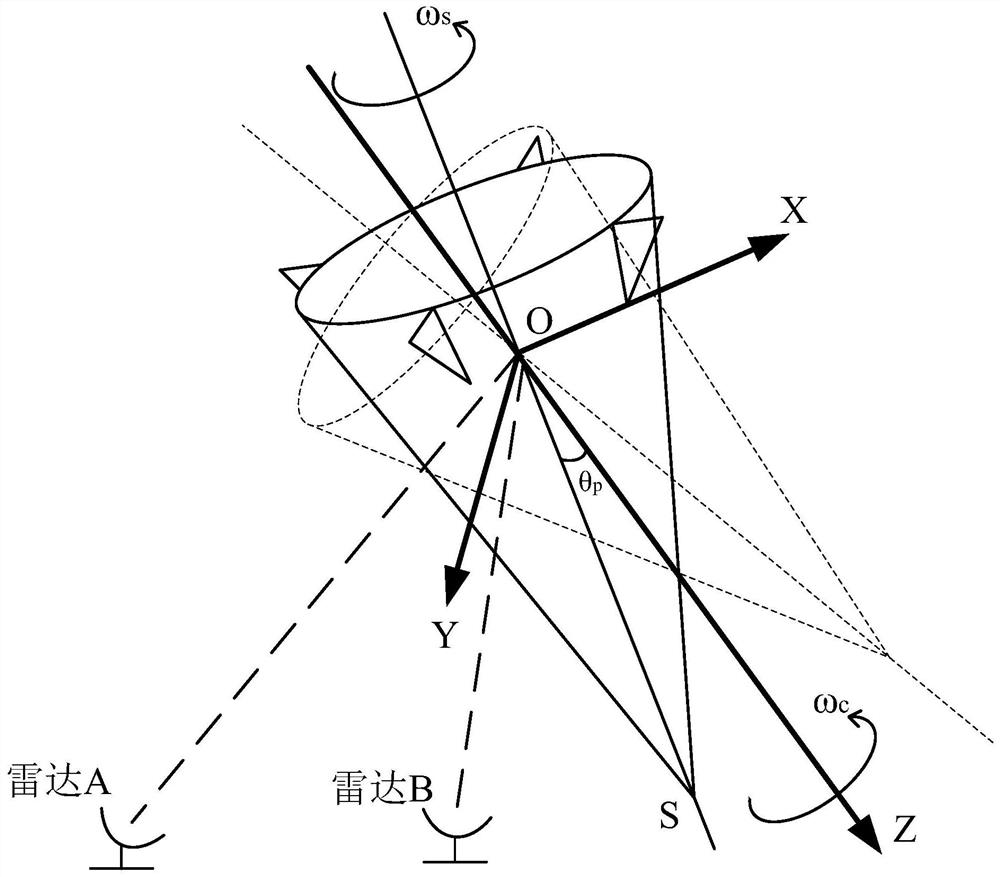
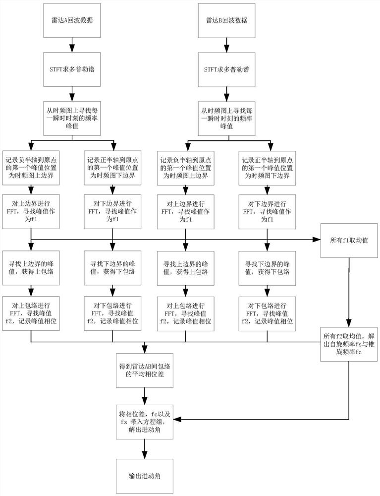
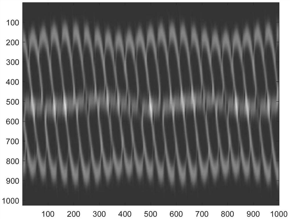
[0114] Specific implementation mode one: combine figure 1 , 2 , 3, 4, 5, 6, 7, and 8 illustrate this embodiment, and the specific process of a method for estimating the precession parameters of a ballistic missile mid-stage target in this embodiment is:

[0115] Such as figure 1 As shown, two radars (hereinafter referred to as radar A and radar B) are used to detect the target in the middle of the ballistic trajectory. The coordinate system OXYZ is established with the target center of mass O as the origin and the precession axis OZ as the Z axis. The warhead around the axis of symmetry OS at an angular velocity ω s Do spin motion, and at the same time its symmetry axis OS revolves around the precession axis OZ at an angular velocity ω c Cone motion, the included angle between radar A line of sight OA and precession axis OZ is θ A , the angle between the line of sight OB of radar B and the precession axis OZ is θ B , the angle between the axis of symmetry OS and the axis...

specific Embodiment approach 2

[0154] Specific embodiment 2: The difference between this embodiment and specific embodiment 1 is that in the step 1, the three-dimensional coordinates of the target relative to the radar A are recorded [X A ,Y A ,Z A ], and the three-dimensional coordinates relative to radar B [X B ,Y B ,Z B ]; then calculate the cosine value COS of the angle ∠AOB between radar A relative to the target direction and radar B relative to the target direction AB , the specific formula:

[0155]

[0156] Other steps and parameters are the same as those in Embodiment 1.

specific Embodiment approach 3

[0157] Specific implementation mode three: the difference between this implementation mode and specific implementation mode one or two is that in the step five, the method obtained by using the step three and obtained in step 4 Calculate the target spin frequency The expression is:

[0158]

[0159] Other steps and parameters are the same as those in Embodiment 1 or Embodiment 2.


PUM


Abstract

The invention relates to a method for estimating precession parameters of middle-section targets of ballistic missiles, in particular to a method for estimating the precession parameters of the middle-section targets of the ballistic missiles. The objective of the invention is to solve the problems that an existing precession feature estimation method cannot utilize the micro-motion features of general scattering points such as an empennage and the like, and the existing precession feature estimation method is low in identification capability for true and false targets. The method comprises the following steps: 1, calculating a cosine value of an included angle between a radar A relative target direction and a radar B relative target direction; 2, obtaining a radar Doppler spectrum; 3, obtaining a boundary spectrum, searching the position of a frequency peak value, and taking the mean value of the position of the frequency peak value; 4, calculating the estimation result of the target coning frequency, and recording the phase of the frequency spectrum at the peak value position at the same time; 5, calculating the spin frequency of the target; taking a phase difference average value; 6, substituting all known parameters into the equation set, and solving thetaA, thetaB, thetaC and thetaP. The method is used in the field of signal processing.

Description

technical field [0001] The invention relates to a method for estimating the precession parameters of a target in the middle of a ballistic missile. Background technique [0002] The typical flight process of a ballistic missile is generally divided into three parts: boost phase, mid-phase and re-entry phase. Among them, the boost phase is usually in the enemy's control area, and the duration of the re-entry phase is extremely short. The middle segment of the trajectory lasts the longest in the entire flight phase, and the trajectory of the trajectory is stable. It is the best stage for the ballistic missile defense system to identify, track, and intercept. However, modern ballistic missiles often release a large number of decoys at the end of the boost phase. The electromagnetic properties of these decoys are the same as those of real warheads, and they have a trajectory similar to that of warheads in a vacuum, which poses considerable difficulties to the defense of ballis...

Claims


Application Information

Patent Timeline
Patent Type & Authority Applications(China)
IPC IPC(8): G01S7/41
CPCG01S7/418G01S7/415
Inventor 王勇张荣政
Owner HARBIN INST OF TECH
Why Eureka
Try Eureka