Cargo carrying device

A technology for handling devices and goods, applied in the directions of transportation and packaging, load hanging components, etc., can solve the problems of cumbersome operation of hooks, manual removal, and high safety risks, and achieve the effect of convenient operation.

Active Publication Date: 2021-11-12
徐州锐尔五金工具制造有限公司
View PDF6 Cites 0 Cited by
  • Summary
  • Abstract
  • Description
  • Claims
  • Application Information

AI Technical Summary

Problems solved by technology

[0005] Therefore, the technical problem to be solved by the present invention is that when a crane is used to carry goods, the operation of the hook is cumbers...

Method used


Image

  • Cargo carrying device
  • Cargo carrying device
  • Cargo carrying device

Examples


Embodiment 1

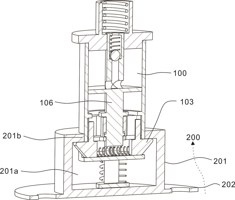
[0028] This embodiment provides a cargo handling device, which includes a picking unit 100 and a fixing unit 200 .

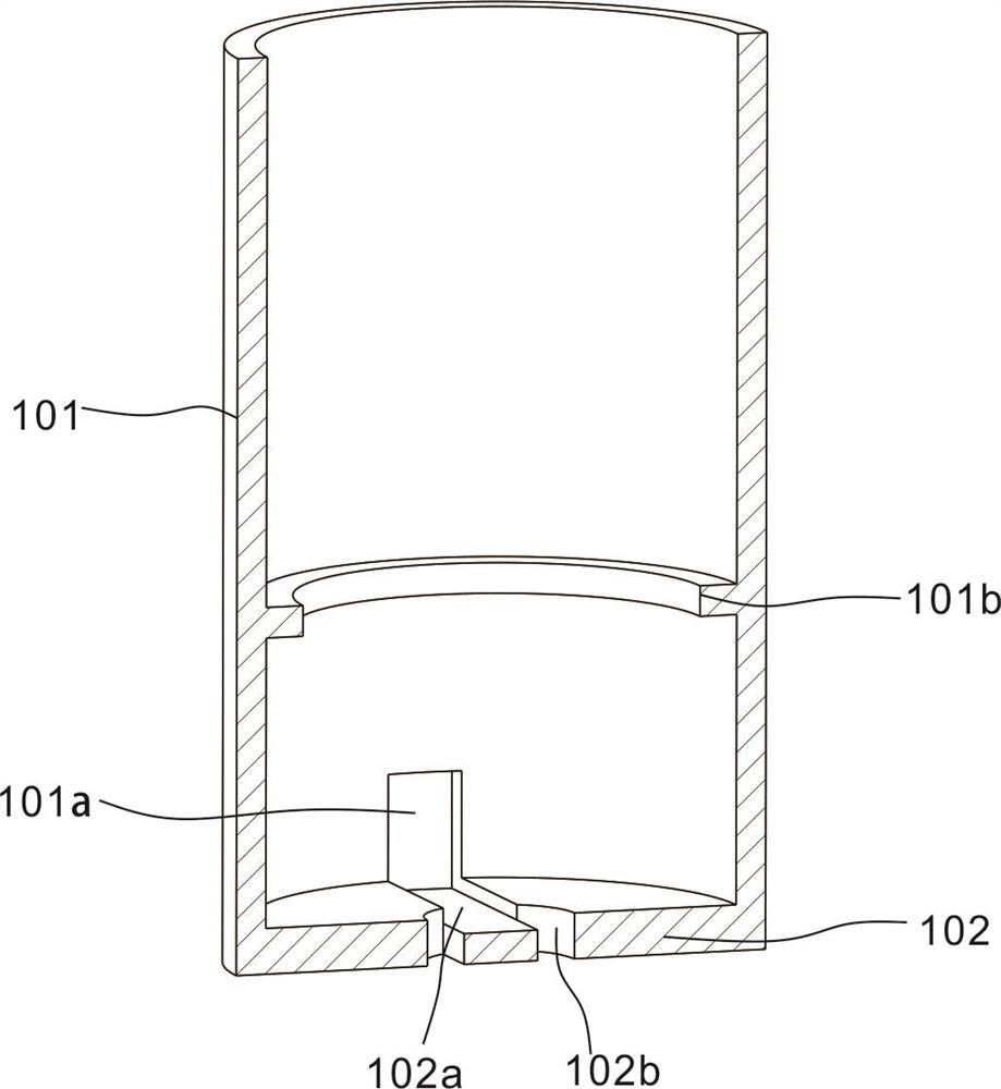
[0029] refer to figure 1 , figure 2 , the extraction unit 100 includes an extraction cylinder 101, the extraction cylinder 101 is cylindrical, the interior of the extraction cylinder 101 is provided with a cylindrical cavity, the bottom of the extraction cylinder 101 is provided with a bottom plate 102, and two through grooves 101a are symmetrically arranged on the side wall of the extraction cylinder 101 The slot 101a is provided with a block 103, two blocks 103 are arranged symmetrically, the block 103 can move radially in the slot 101a, and the moving directions of the two blocks 103 are opposite.

[0030] refer to figure 1 , the fixing unit 200 includes a fixing block 201 and a flange 202 connected to the lower end of the fixing block 201 . The flange plate 202 is fixed on the goods to be transported, and the fixing here can be through but not limited to...

Embodiment 2

[0035] The embodiment is based on the previous embodiment, and the difference from the previous embodiment is that in this embodiment, after the goods are lifted and transported to the designated location, the goods can be dropped off again for the next transport. The specific structure of this embodiment is as follows.

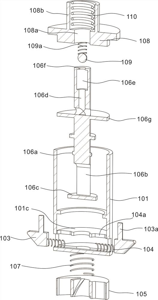
[0036] combine image 3A partition 101c is arranged inside the extracting cylinder 101, and the clamping block 103 is located between the partition 101c and the bottom plate 102 to prevent tilting. The partition 101c is provided with two long slots 104a in the radial direction, and the block 103 is provided with a pin shaft 103a extending axially along the extraction cylinder 101, and the pin shaft 103a passes through the corresponding long slots 104a. The position of the block 103 is adjusted by controlling the pin shaft 103a.

[0037] combine image 3 , Figure 4 A turntable 105 is connected above the partition 101c, the turntable 105 is disc-shaped, an...

Embodiment 3

[0041] The embodiment is based on the previous embodiment, and the difference from the previous embodiment is that this embodiment includes a transmission rod 106 arranged in the extracting cylinder 101 to drive the movement of the turntable 105 .

[0042] refer to image 3 , Figure 4 , the turntable 105 is provided with a first through hole 105e, the transmission rod 106 passes through the first through hole 105e and the partition 101c, the inner wall of the first through hole 105e is provided with a spiral groove 105f along the helical line, and the transmission rod 106 is provided with The protrusion 106a is inserted into the spiral groove 105f, and the axial movement of the transmission rod 106 can be transformed into the rotation of the turntable 105 .

[0043] refer to figure 2 , image 3 , in order to provide installation space for the first spring 104, the end of the transmission rod 106 close to the bottom plate 102 is provided with an avoidance groove 106b, and ...


PUM


Abstract

The invention discloses a cargo carrying device. The cargo carrying device comprises an extracting unit and a fixing unit, wherein the extracting unit comprises an extraction barrel, the interior of the extraction barrel is a cavity, a bottom plate is arranged at the bottom of the extraction barrel, a through groove is formed in the side face of the extraction barrel, a clamping block is arranged in the through groove, the clamping block moves in the direction perpendicular to the axis of the extraction barrel, the fixing unit comprises a fixing block and a flange plate connected to the fixing block, the fixing block is provided with a circular groove, a boss extending in the axis direction is arranged at the opening position of the circular groove, the lower end of the extraction barrel can stretch into the circular groove, and the clamping blocks make contact with the inner wall of the boss. When cargos are carried through the cargo carrying device, the cargos are directly lifted and carried by operating the extraction barrel, after the cargos are carried to a designated place, falling can be completed only by operating the extraction barrel to move downwards again, and the operation process is extremely convenient and fast.

Description

technical field [0001] The invention relates to the field of cargo handling, in particular to a cargo handling device. Background technique [0002] Industrial freight is an important part of industry. Industrial transportation, also known as in-factory transportation, refers to the transportation carried out in the production process within factories and enterprises, and is an important part of the production activities of industrial and mining enterprises. At present, most of the industrial cargo handling is carried out by manual handling or cranes. Manual handling requires a lot of labor and the production efficiency is relatively low. Manual dismantling is required, which affects work efficiency and poses a high safety risk. Contents of the invention [0003] The purpose of this section is to summarize some aspects of the embodiments of the present invention and briefly introduce some preferred embodiments. Some simplifications or omissions may be made in this section...

Claims


Application Information

Patent Timeline
IPC IPC(8): B66C1/10
CPCB66C1/10
Inventor 高巧英高玮鸿高星
Owner 徐州锐尔五金工具制造有限公司
Why Eureka
Try Eureka