Forklift portal frame with buffer structure

A technology of buffer structure and forklift gantry, which is applied in the direction of lifting device, spring/shock absorber, vibration suppression adjustment, etc. It can solve the problems of large load of oil pump, less change of hydraulic oil flow rate, increase of hydraulic oil flow rate, etc., and achieve easy and slow The effects of shutdown, prevention of high pressure in the pipe, and ease of installation

Active Publication Date: 2021-11-12
NINGBO RUYI
View PDF8 Cites 1 Cited by
  • Summary
  • Abstract
  • Description
  • Claims
  • Application Information

AI Technical Summary

Problems solved by technology

[0005] The buffer device reduces the flow rate of the hydraulic oil by reducing the diameter of the pipeline through which the hydraulic oil flows, resulting in a decrease in the output speed of the hydraulic cylinder. However, the flow rate of the hydraulic oil will increase, resulting in little change in the flow rate of the hydraulic oil. The purpose of reducing the output speed of the hydraulic cylinder will also cause a large load to the oil pump, which will affect the stable operation and life of the oil pump, and will cause the temperature of the hydraulic oil at the narrow diameter to rise

Method used


Image

  • Forklift portal frame with buffer structure
  • Forklift portal frame with buffer structure
  • Forklift portal frame with buffer structure

Examples


Embodiment Construction

[0043] In order to further understand the features, technical means, and specific objectives and functions achieved by the present invention, the present invention will be further described in detail below in conjunction with the accompanying drawings and specific embodiments.

[0044] Such as figure 1 , figure 2 , image 3 , Figure 4 and Figure 5 Shown:

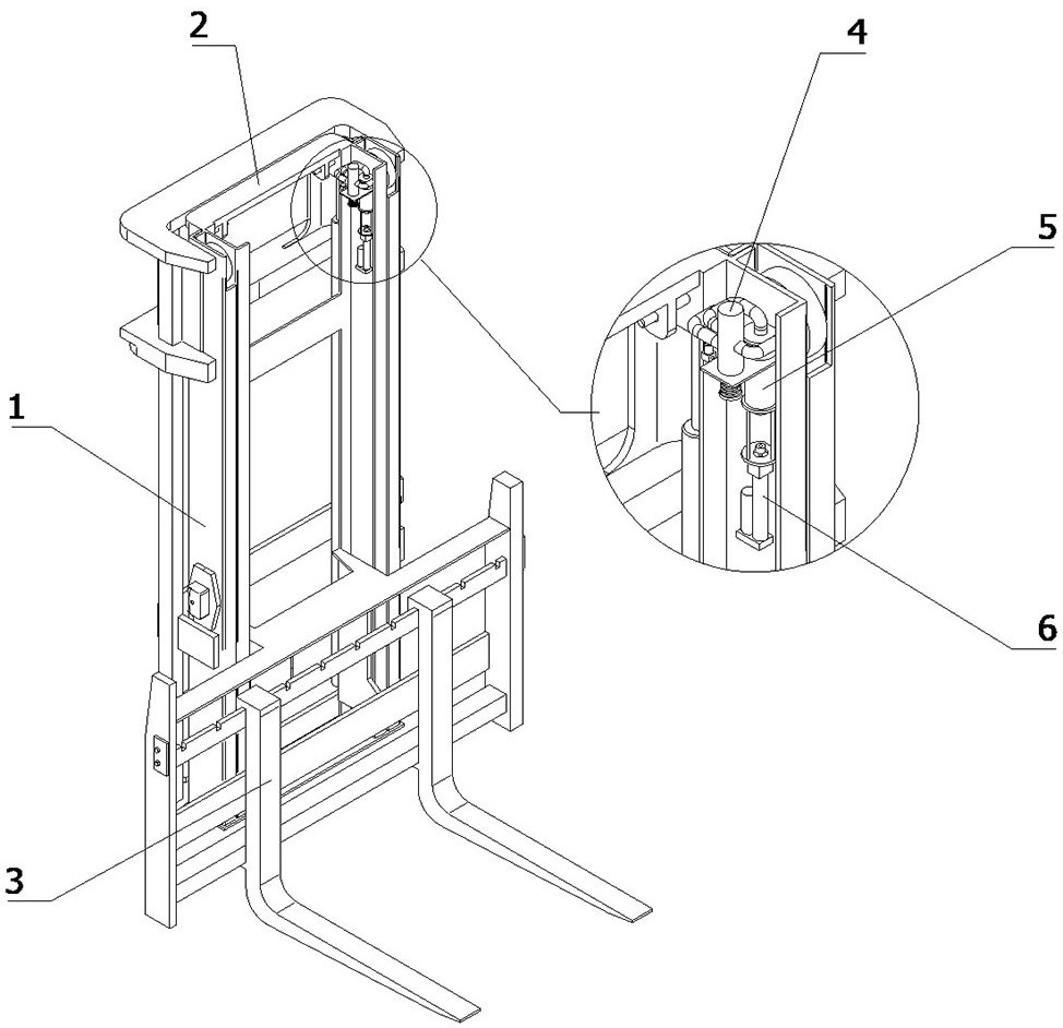
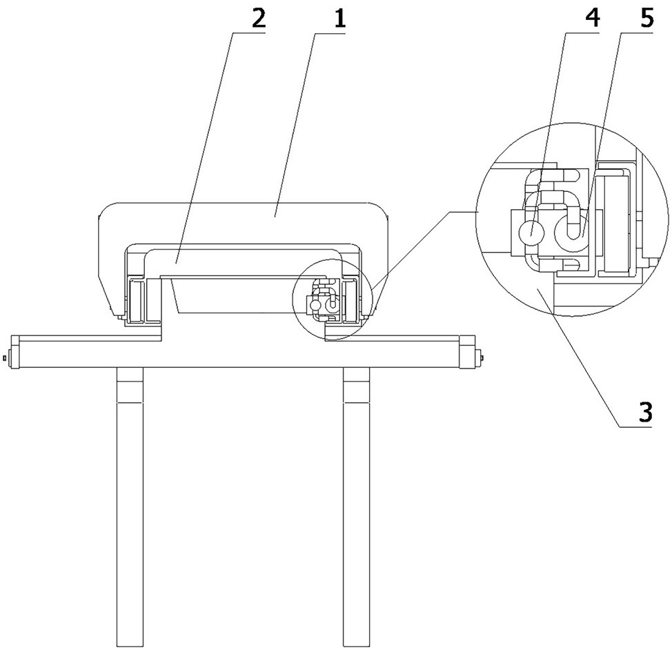
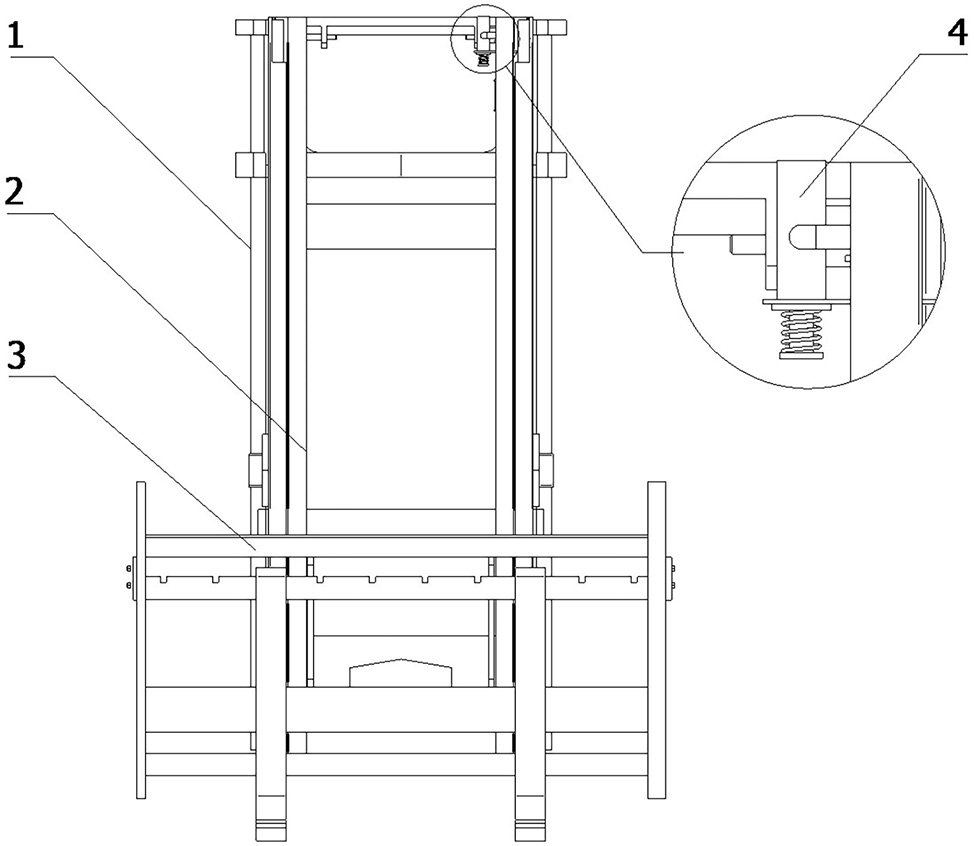
[0045] A forklift mast with a buffer structure, comprising an outer mast 1, an inner mast 2, and a fork frame 3 that are slidably arranged in sequence, and is used to drive the inner mast 2 to slide relative to the outer mast 1 and to be opposite to the fork frame 3 The hydraulic cylinder that the inner mast 2 slides, and the oil pump used to drive the output of the hydraulic cylinder, the buffer structure, the buffer structure includes a flow divider 4, an accumulator 5 and an energy release device 6, and the flow divider 4 is arranged on the outer mast 1 and At the top of the inner mast 2, the flow divider 4 includ...


PUM


Abstract

The invention relates to the technical field of forklifts, in particular to a forklift portal frame with a buffer structure. The forklift portal frame comprises an outer portal frame, an inner portal frame, a fork arm carrier, a hydraulic cylinder, an oil pump and the buffer structure, the buffer structure comprises a flow divider, an energy accumulator and an energy releaser, the flow divider is arranged at the top ends of the outer portal frame and the inner portal frame, the flow divider comprises a trigger part, the flow divider further comprises an oil inlet, an oil outlet and an oil dividing opening, the oil inlet is communicated with the oil conveying end of the oil pump, and the oil outlet is communicated with one communicating opening of the hydraulic cylinder. The energy accumulator comprises an energy storage part, the energy storage part is communicated with the oil dividing opening, and the energy accumulator further comprises a conduction part which can move relative to the outside in an energy storage state; and the energy releaser is arranged at one side of the energy accumulator, the energy releaser comprises a driving part, the flow divider in the buffering structure conducts flow division on hydraulic oil between the oil pump and the hydraulic cylinder, the hydraulic oil is stored in the energy accumulator, the load of the oil pump does not need to be increased, and the buffering structure is stable and easy to install.

Description

technical field [0001] The invention relates to the technical field of forklifts, in particular to a forklift mast with a buffer structure. Background technique [0002] The lifting system used by the forklift includes the forklift mast. When the forklift mast is lifted to the top, that is, after the oil cylinder travels, it will cause a large impact due to inertia and heavy objects, which will cause vibration of the whole vehicle, resulting in The driver is uncomfortable; in addition, the impact also affects the safety and stability of the cargo. [0003] At present, few forklift lifting systems have an upper buffer mechanism when the mast is lifted to the top, and only a few realize the buffer function through the lifting cylinder. Specifically, the throttling technology is used inside the cylinder, which has a complex structure, difficult processing, and high cost. , Once the oil cylinder has a problem, the buffer will also lose its effect, so it is not reliable. [000...

Claims


Application Information

Patent Timeline
Patent Type & Authority Applications(China)
IPC IPC(8): B66F9/22B66F9/12B66F9/08B66F9/075F16F15/023F16F15/067
CPCB66F9/22B66F9/122B66F9/08B66F9/07504F16F15/023F16F15/067F16F15/022
Inventor 叶国云储江郭宏斌叶青云傅敏
Owner NINGBO RUYI
Why Eureka
Try Eureka