

On-line tar removal device and method for heat accumulators
A technology of regenerator and regenerator, which is applied in lighting and heating equipment, etc., can solve the problems of energy consumption, time-consuming, discontinuous production, etc., so as to improve the working temperature, prolong the coke cleaning cycle, and reduce the coke cleaning workload. Effect
- Summary
- Abstract
- Description
- Claims
- Application Information
AI Technical Summary
Problems solved by technology
Method used
Image

Examples
Embodiment Construction
[0016] The present invention will be further described below in conjunction with the accompanying drawings and embodiments.
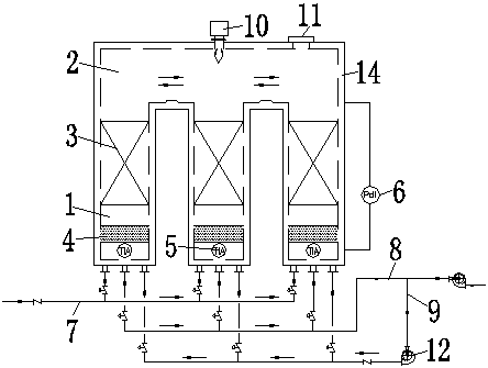
[0017] Such as figure 1 As shown, a kind of on-line decoking device for regenerator according to the present invention includes an incinerator main body, and the incinerator main body includes a regenerator 1 and a combustion chamber 2, and in the regenerator 1 The upper part is provided with a rectangular hole ceramic regenerator 3, a ceramic saddle ring packing layer 4 is provided at the bottom of the regenerator chamber 1, and a temperature thermocouple 5 is provided below the ceramic saddle ring packing layer 4. An online differential pressure gauge 6 is provided between the bottom of the ring packing layer 4 and the top of the ceramic regenerator 3 with rectangular holes. One end of the exhaust pipe 8 is connected to one end of the blowback pipe 9, a burner 10 and an explosion-proof door 11 are arranged on the top of the main body of the incinerat...
PUM
 Abstract
Description
Claims
Application Information