Muddy water extraction device

A technology for extracting equipment and muddy water, which is applied in the direction of wellbore/well components, earthwork drilling and mining, etc. It can solve the problems of damage to the camera device, blocking the line of sight of the camera device, etc., and achieve the effect of rapid extraction, small impact, and prevention of water leakage

Pending Publication Date: 2021-11-12
SHENZHEN TRAFFIC CONSTR ENG TEST & DETECTION CENT
View PDF0 Cites 0 Cited by
  • Summary
  • Abstract
  • Description
  • Claims
  • Application Information

AI Technical Summary

Problems solved by technology

[0003] The purpose of the embodiments of the present application is to provide a muddy water extraction device to solve the problems in the related art that the muddy water in the borehole blocks the sight of the camera device, easily causes damage to the camera device, and makes it difficult to comprehensively determine the defects at the bottom of the pile

Method used


Image

  • Muddy water extraction device
  • Muddy water extraction device
  • Muddy water extraction device

Examples


Embodiment 1

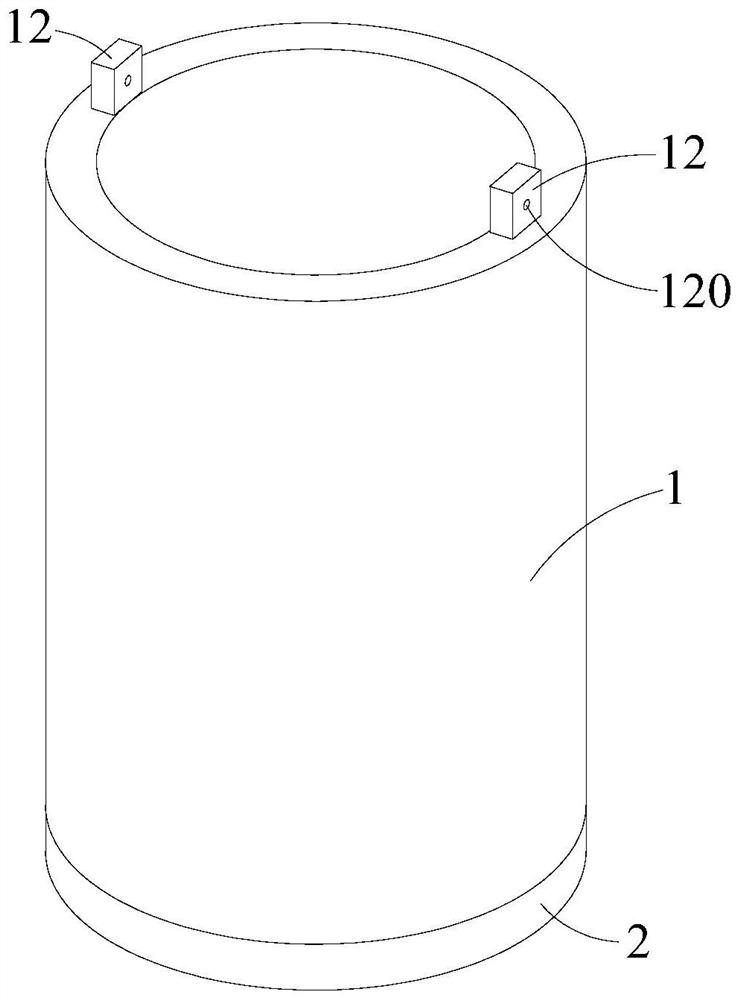
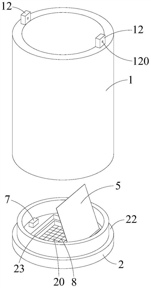
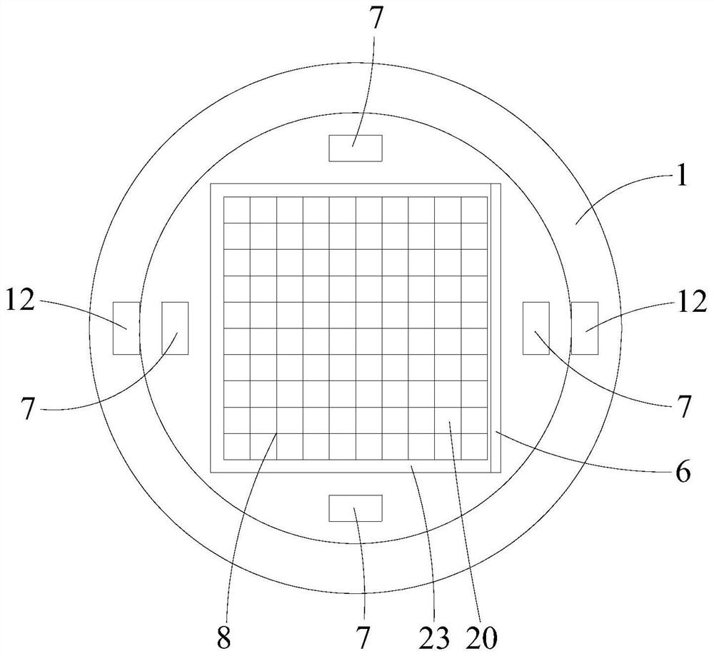
[0045] see Figure 2 to Figure 4, the muddy water extraction device provided in Embodiment 1 of the present application will now be described. The muddy water extracting device includes a casing 1 with an accommodating chamber and a base 2 connected to one end of the casing 1 ; the base 2 is provided with an opening 20 communicating with the accommodating chamber of the casing 1 . The muddy water extraction device also includes a cover plate 5 for covering the opening 20 and a stopper 6 for limiting the rotation angle of the cover plate 5; On the side of the chamber, the limit stopper 6 is installed on the base 2. Among them, the casing 1 and the base 2 are detachably connected, such as through bolt connection, buckle connection, etc., which facilitate the quick disassembly and assembly of the base 2, and the replacement of the drill bit to realize the drilling operation and realize the multi-purpose of the mud water extraction device . With this structure, the present appl...

Embodiment 2

[0053] see Figure 7 , Figure 9 and Figure 10 Now, the muddy water extracting device provided in the second embodiment of the present application will be described. The difference between the muddy water extraction device provided in the second embodiment of the present application and the muddy water extraction device provided in the first embodiment is that the muddy water extraction device also includes a connecting pipe 3 sleeved on the casing 1, and the inner side wall of the connecting pipe 3 faces the casing. The direction of the pipe 1 is protrudingly provided with a first retaining ring 31 and a second retaining ring 32, and the first retaining ring 31 and the second retaining ring 32 are arranged at intervals; 31 or the second stop ring 32 cooperates with the third stop ring 13 to limit the movement stroke of the connecting pipe 3 , and the third stop ring 13 is arranged between the first stop ring 31 and the second stop ring 32 . With this structure, by sheathi...

Embodiment 3

[0058] see Figure 12 to Figure 14 Now, the muddy water extracting device provided in the third embodiment of the present application will be described. The difference between the muddy water extraction device provided in the third embodiment of the present application and the muddy water extraction device provided in the first embodiment is that the muddy water extraction device also includes an extension pipe 4 sleeved on the casing 1, and the outer wall of the casing 1 is along the The axial direction of the sleeve 1 is provided with a first guide groove 15, and the inner side wall of the extension pipe 4 is correspondingly installed with a guide block 41 extending into the first guide groove 15; A second guide groove 16 for sliding the guide block 41 is also provided in the circumferential direction, and the first guide groove 15 communicates with the second guide groove 16 . With this structure, the extension pipe 4 can move up and down along the casing 1 along the first...


PUM


Abstract

The invention provides a muddy water extraction device. The muddy water extraction device comprises a sleeve, a base connected with one end of the sleeve, a cover plate and a limiting stop block; an open hole is formed in the base; the cover plate is used for covering the open hole; the limiting stop block is used for limiting the rotating angle of the cover plate; and the open hole communicates with the sleeve, and the cover plate is hinged to the side face, facing the sleeve, of the base. The open hole is formed in the base, and when the sleeve extends into a drill hole, muddy water at the bottom of the hole pushes open the cover plate under the action of pressure and enters the sleeve through the open hole; and in the ascending process of the sleeve, the cover plate can be tightly pressed on the open hole under the action of the gravity of the limiting check block and the pressure of muddy water, so that the open hole is covered, and water leakage is prevented. The rotation angle of the cover plate can be limited through the limiting stop block, and the situation that resetting cannot be achieved due to excessive rotation is avoided. Therefore, through the muddy water extraction device, rapid extraction of the muddy water at the bottom of the hole can be achieved, an operator can conveniently and comprehensively judge the defects of the bottom of a pile through a camera device, and the influence degree on the camera device is small.

Description

technical field [0001] The application belongs to the technical field of engineering drilling, and more specifically relates to a muddy water extraction device. Background technique [0002] When the current water drilling rig is drilling and coring, if there are unfavorable situations such as pile body defects such as mud inclusion or the bearing layer of the pile is strongly weathered, there will be more mud and water inside the borehole, which will block the line of sight of the camera device in the hole, making the operation difficult. The personnel cannot see the pile body defects clearly, especially when close to the bottom of the hole, the muddy water at the bottom makes the operator unable to accurately determine the distance between the hole bottom and the end of the pile body, which not only easily causes damage to the camera device in the hole, but also makes it difficult to comprehensively analyze the pile bottom defects determination. Contents of the invention...

Claims


Application Information

Patent Timeline
IPC IPC(8): E21B27/00
CPCE21B27/005
Inventor 黎木平侯茜茜陈小冬周斐陈伟易明明
Owner SHENZHEN TRAFFIC CONSTR ENG TEST & DETECTION CENT
Why Eureka
Try Eureka