Eureka AIR delivers breakthrough ideas for toughest innovation challenges, trusted by R&D personnel around the world.

Speed reducer for punching machine

A technology of reducer and stamping machine, which is applied in the direction of mechanical equipment, transmission parts, gear transmission, etc., can solve the problems of complex structure of planetary reducer, unfavorable installation and maintenance, and prolonging the installation and debugging time of reducer, etc., to achieve The effect of simple structure, large torque and convenient installation

Pending Publication Date: 2021-11-12
宁波澳玛特高精冲压机床股份有限公司
View PDF1 Cites 0 Cited by
  • Summary
  • Abstract
  • Description
  • Claims
  • Application Information

AI Technical Summary

Problems solved by technology

[0004] However, the complex structure of the planetary reducer is not conducive to subsequent installation and maintenance, and there is only one input shaft that can only be connected to one drive motor. When the torque required by the equipment exceeds the rated torque of the existing drive motor, the original drive The motor cannot be used, and in most cases, when the ordinary reducer is used, it needs to be used with an additional one-stage reducer to prevent the reducer from burning out due to excessive initial load, which lengthens the reducer installation and commissioning time

Method used


Image

  • Speed reducer for punching machine
  • Speed reducer for punching machine
  • Speed reducer for punching machine

Examples


Embodiment Construction

[0026] Below are specific embodiments of the present invention and in conjunction with accompanying drawing, technical scheme of the present invention is described further, but the present invention is not limited to these embodiments.

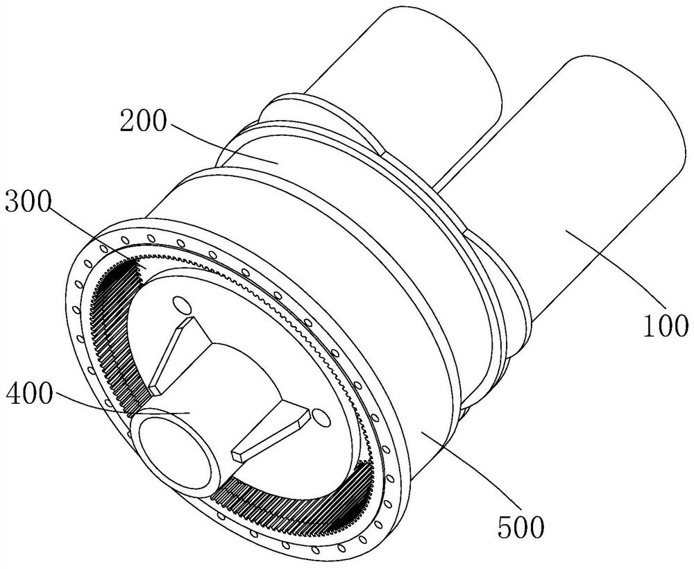
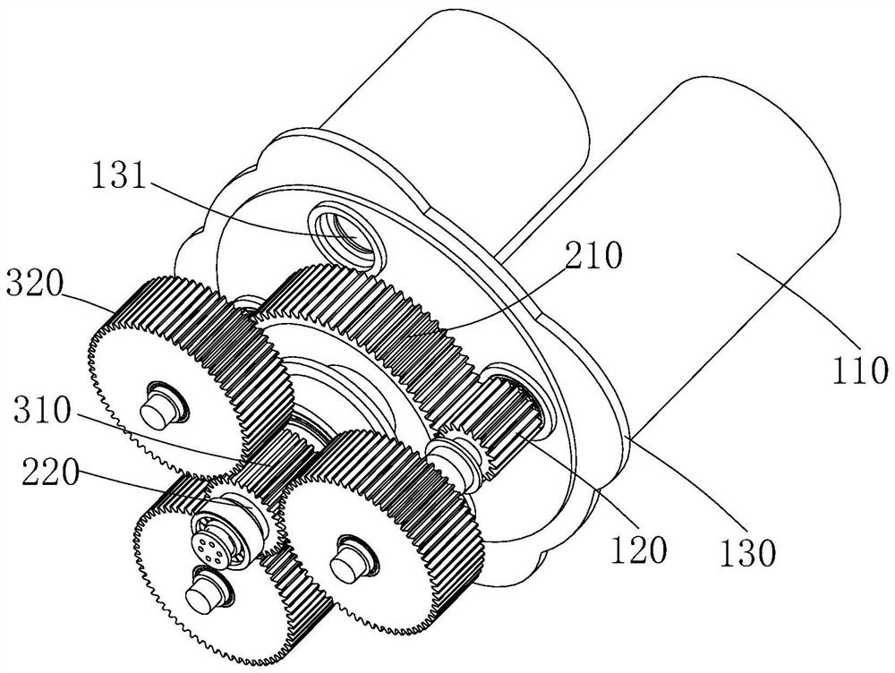
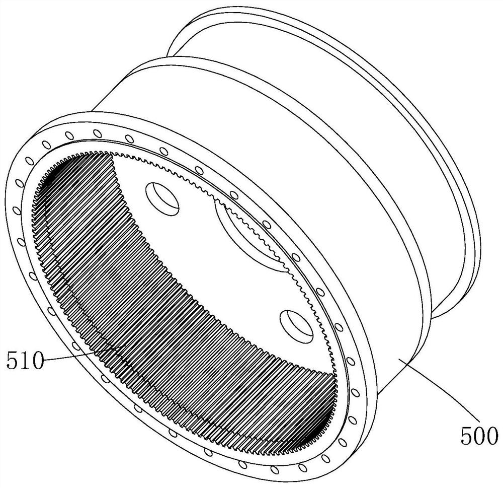
[0027] like Figure 1 to Figure 5 As shown, in this solution, the reduction gear is mainly described in detail for the punching machine, but the reduction gear of the present invention is not limited to the application in the reduction gear, as long as it includes a motor drive device, it can be used, such as cars etc.

[0028] A speed reducer for a stamping machine of the present invention includes: a power input mechanism 100, a primary speed reduction mechanism 200, a secondary speed reduction mechanism 300 and a power output mechanism 400.

[0029] The power input mechanism 100 is detachably provided with several driving motors 110, and the output end of each driving motor 110 is provided with a main gear 120, and the driving motor 110 is...


PUM


Abstract

The invention relates to the technical field of punching equipment, and provides a speed reducer for a punching machine. The speed reducer comprises a power input mechanism, wherein a plurality of driving motors are detachably arranged on the power input mechanism, and the output end of each driving motor is provided with a main gear; a first-stage speed reducing mechanism provided with first driven wheels meshed with the main gears; a second-stage speed reducing mechanism provided with a second driven wheel, wherein the second driven wheel is connected with the first driven wheels through first rotating shafts, and a plurality of third driven wheels are arranged on the outer side of the second driven wheel; and a power output mechanism arranged on the second-stage speed reducing mechanism in a sleeving manner. Compared with the prior art, the speed reducer mainly has the following advantages that the plurality of driving motors can be loaded at the same time, and larger torque can be provided on the premise that parameters of the gears on the speed reducing mechanisms are not changed; and compared with a mode of a first-stage speed reducing mechanism of a traditional speed reduction rack, the speed reducer is simpler in structure and more convenient to install.

Description

technical field [0001] The invention relates to the technical field of stamping equipment, in particular to a speed reducer for a stamping machine. Background technique [0002] The reducer is a power transmission mechanism that does not generate power itself. Its function is to reduce the number of revolutions of the motor (motor) to the desired number of revolutions by using gears of different sizes and speed converters, and obtain a larger speed. moment mechanism. The reason why the reducer is used instead of the motor directly connected to the equipment is because if the motor is directly connected to the equipment, when the equipment is running, the load on the motor is very large, which will cause great damage to the motor, and After the reducer is different, for example, the reducer with a reduction ratio of 100, the speed ratio of the reducer = input speed / output speed, if the speed ratio is 100, the output torque is about 100 of the input torque times. (the speed...

Claims


Application Information

Patent Timeline
Patent Type & Authority Applications(China)
IPC IPC(8): F16H1/32F16H57/08
CPCF16H1/32F16H57/08F16H2001/327
Inventor 杨天宇桂前锦付亮钟梁星
Owner 宁波澳玛特高精冲压机床股份有限公司
Why Eureka
Eureka Blog
Learn More