
Fatigue crack identification method and system

A fatigue crack and identification method technology, applied in the field of fatigue crack identification methods and systems, can solve the problems of large workload of sample extraction, unrepresentative, and inability to identify fatigue cracks of structures to be measured.

Pending Publication Date: 2021-11-12
WUHAN INSTITUTE OF TECHNOLOGY
View PDF0 Cites 0 Cited by
  • Summary
  • Abstract
  • Description
  • Claims
  • Application Information

AI Technical Summary

Problems solved by technology

[0004] In order to solve the problem that when Lamb waves are used to detect micro-defects in thin plate structures, the sample extraction workload is large and not representative, and the fatigue cracks of the structure to be tested cannot be effectively identified. The present invention provides a fatigue crack identification method and system.

Method used


Image

  • Fatigue crack identification method and system
  • Fatigue crack identification method and system
  • Fatigue crack identification method and system

Examples


Embodiment Construction

[0043] The following examples are further explanations and supplements to the present invention, and do not constitute any limitation to the present invention.

[0044] A fatigue crack identification method according to an embodiment of the present invention will be described below with reference to the accompanying drawings.

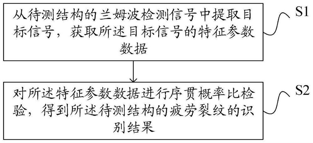
[0045] refer to figure 1 As shown, the present invention provides a fatigue crack identification method, comprising:

[0046] S1. Extract the target signal from the Lamb wave detection signal of the structure to be tested, and obtain the characteristic parameter data of the target signal;

[0047] S2. Performing a sequential probability ratio test on the characteristic parameter data to obtain an identification result of the fatigue crack of the structure to be tested.

[0048] The fatigue crack identification method provided by the above embodiment uses the characteristic parameter data to reflect the information characteristics of the fatigue crack ...


PUM


Abstract

The invention relates to a fatigue crack identification method and system, and the method comprises the steps: extracting a target signal from a Lamb wave detection signal of a to-be-detected structure, and obtaining the feature parameter data of the target signal; and performing sequential probability ratio test on the characteristic parameter data to obtain an identification result of the fatigue crack of the to-be-tested structure. By means of the method, the information characteristics of fatigue crack damage are reflected by utilizing the characteristic parameter data, and the fatigue crack of the to-be-detected structure is effectively identified in combination with the sequential probability ratio test, so that the sample extraction workload is reduced, and the fatigue crack identification efficiency is improved.

Description

technical field [0001] The invention relates to the technical field of nondestructive testing, in particular to a fatigue crack identification method and system. Background technique [0002] With the rapid development of society, the requirements for parts in the fields of chemical industry and machinery are also gradually increasing. Considering the factors of operation cost and safety, using various non-destructive testing methods, regular reliability maintenance of these equipment structures has become more and more important in production and life. increasingly important issue. Compared with many other non-destructive testing technologies, ultrasonic testing technology has more advantages and is widely used. The principle of ultrasonic testing technology is to detect the changes of interface reflection or energy attenuation caused by ultrasonic waves propagating in the medium and encountering defects. After research, it is found that nonlinear ultrasonic testing techno...

Claims


Application Information

Patent Timeline
Patent Type & Authority Applications(China)
IPC IPC(8): G01N29/44G01N29/04
CPCG01N29/4454G01N29/4427G01N29/041
Inventor 陈汉新李森刘明明李梦龙胡振宇
Owner WUHAN INSTITUTE OF TECHNOLOGY
Learn More