Winding equipment for motor stator core

A motor stator and stator core technology, applied in the field of machinery, can solve the problems of poor air permeability of silicon steel sheet, low self-heating efficiency, and affecting the winding and forming effect of stator core, so as to achieve the effect of improving the fit and cleaning quality

Active Publication Date: 2021-12-21
NANTONG HUDA MASCH EQUIP CO LTD
View PDF4 Cites 0 Cited by
  • Summary
  • Abstract
  • Description
  • Claims
  • Application Information

AI Technical Summary

Problems solved by technology

[0003] In the prior art, when the stator core is wound by the silicon steel sheet, if the winding operation is carried out in a hot working environment, since the silicon steel sheet is continuously wound on the stator iron core, the air permeability of the silicon steel sheet will be reduced. As the temperature becomes worse, the self-radiation efficiency decreases, which will affect the winding and forming effect of the stator core, and then affect the production efficiency of the overall stator core

Method used


Image

  • Winding equipment for motor stator core
  • Winding equipment for motor stator core
  • Winding equipment for motor stator core

Examples


Embodiment 1

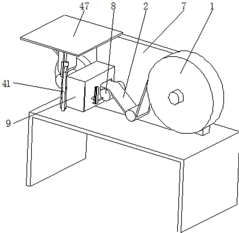
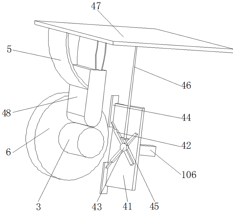
[0029] see Figure 1-6 The present invention provides a technical solution: a winding device for a motor stator core, comprising a winding machine 1 and a stator core 3, an automatic adjustment mechanism is arranged outside the stator core 3, and the automatic adjustment mechanism includes a ventilation plate 41, Telescopic rod 42, rotating column 43, slide plate 44, pull plate 45, pull rod 46, support plate 47 and pressing block 48, telescopic rod 42 runs through and is slidably installed on rotating column 43, and rotating column 43 is rotatably installed on ventilation plate 41 , the top of the telescopic rod 42 is rotatably mounted on the slide plate 44, the slide plate 44 is slidably mounted on the air outlet end of the ventilation plate 41, the pull plate 45 is movably mounted on the outer wall of the telescopic rod 42, the bottom of the pull rod 46 is embedded in the top of the pull plate 45, and the top of the pull rod 46 Embedded in the bottom of the support plate 47,...

Embodiment 2

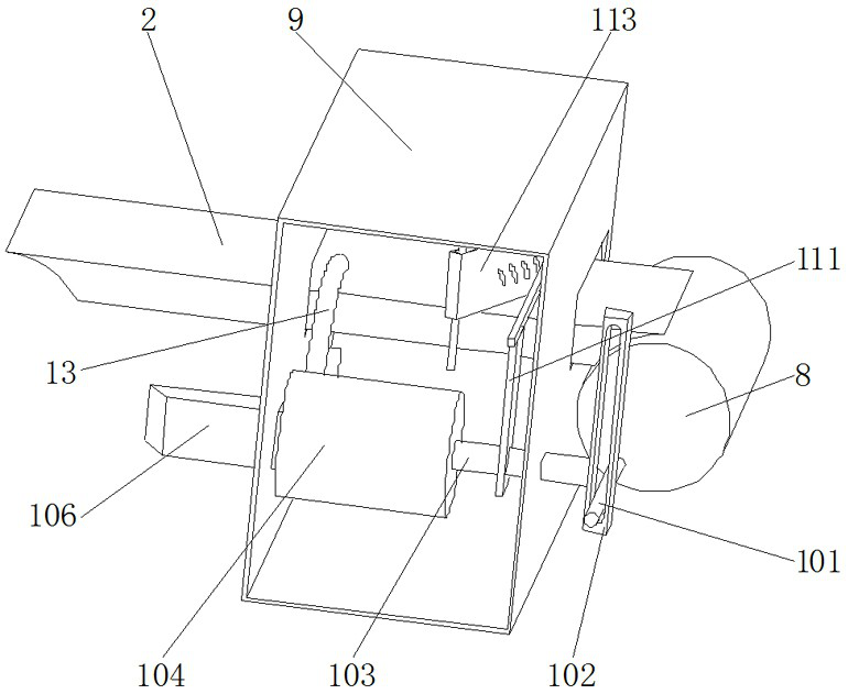
[0032] Such as image 3 , Figure 4 and Figure 5 As shown, on the basis of Embodiment 1, in this embodiment, a cleaning mechanism is provided inside the cleaning box 9, and the cleaning mechanism includes a connecting rod 111, a cleaning column 112, a cleaning scraper 113 and a limit post 114, and one end of the connecting rod 111 Fixedly installed on the push rod 103, the other end of the connecting rod 111 is rotatably installed on the cleaning column 112, the cleaning scraper 113 is embedded on the cleaning column 112, the cleaning scraper 113 is set in a hollow shape, and the inner wall of the cleaning scraper 113 is slidably installed on the On the outer wall of the limiting column 114, the cleaning scraper 113 is arranged in an inclined shape, which can effectively increase the cleaning area of ​​the cleaning scraper 113 and improve the cleaning efficiency. The top of the limiting column 114 is embedded on the inner wall of the cleaning box 9 top, and the cleaning scra...


PUM


Abstract

The invention discloses a winding device for a stator iron core of a motor, which relates to the technical field of machinery. It includes a winding machine and a stator core, and an automatic adjustment mechanism is arranged outside the stator core, and the automatic adjustment mechanism includes a ventilation plate, a telescopic rod, a rotating column, a slide plate, a pull plate, a pull rod, a support plate and a pressing block, The telescopic rod penetrates and is slidably mounted on a rotating column, the rotating post is rotatably mounted on the ventilation plate, the top of the telescopic rod is rotatably mounted on a slide plate, and the slide plate is slidably mounted on the air outlet end of the ventilation plate. The winding equipment for the stator core of the motor can effectively dissipate heat from the wound silicon steel sheet and the stator core by setting an automatic adjustment mechanism outside the stator core without causing waste of wind power resources, and at the same time Through the cleaning mechanism inside the cleaning box, impurities such as engine oil on the surface of the silicon steel sheet can be effectively scraped and cleaned to improve the adhesion of the silicon steel sheet.

Description

technical field [0001] The invention relates to the field of mechanical technology, in particular to a winding device for a stator iron core of a motor. Background technique [0002] Iron core winding machine is a special equipment for silicon steel sheet iron core winding, which can produce annular, rectangular and other shaped iron cores. In order to obtain feasible low hysteresis loss, it needs to be produced under special control conditions. Generally, pure iron is not suitable for alternating magnetic fields, mainly because of its small resistivity, which will cause large eddy current losses. After adding silicon element, since silicon and iron form a solid solution type alloy, the resistivity is increased. Silicon steel sheet is to use the increase of resistivity to reduce the eddy current loss caused by the thickness direction. The eddy current loss is proportional to the thickness of the silicon steel sheet, usually the thickness of the silicon steel sheet used fo...

Claims


Application Information

Patent Timeline
Patent Type & Authority Patents(China)
IPC IPC(8): H02K15/02B08B5/02B08B1/00
CPCH02K15/02B08B1/005B08B5/023
Inventor 吴小波
Owner NANTONG HUDA MASCH EQUIP CO LTD
Why Eureka
Try Eureka