Multidirectional vibration ultrasonic transducer, ultrasonic cleaning device and cleaning method

An ultrasonic transducer and ultrasonic cleaning technology, applied to chemical instruments and methods, cleaning methods using liquids, cleaning methods and utensils, etc., can solve problems such as incomplete cleaning, cleaning dead ends, single vibration direction, etc., to achieve thorough cleaning , avoid standing wave, high vibration frequency effect

Active Publication Date: 2021-11-19
SHAANXI NORMAL UNIV
View PDF12 Cites 0 Cited by
  • Summary
  • Abstract
  • Description
  • Claims
  • Application Information

AI Technical Summary

Problems solved by technology

[0003] In the field of ultrasonic cleaning technology, if the current piezoelectric transducer is used for cleaning, due to the single vibration direction, a standing wave will be generated between the bottom of the cleaning tank and the liquid level of the liquid in the cleaning tank, and the standing wave will have nodes. There is no vibration at the wave node, and it is easy to form a cleaning dead angle, resulting in incomplete cleaning

Method used


Image

  • Multidirectional vibration ultrasonic transducer, ultrasonic cleaning device and cleaning method
  • Multidirectional vibration ultrasonic transducer, ultrasonic cleaning device and cleaning method
  • Multidirectional vibration ultrasonic transducer, ultrasonic cleaning device and cleaning method

Examples


Embodiment 1

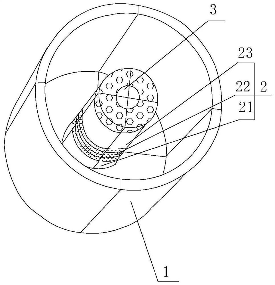
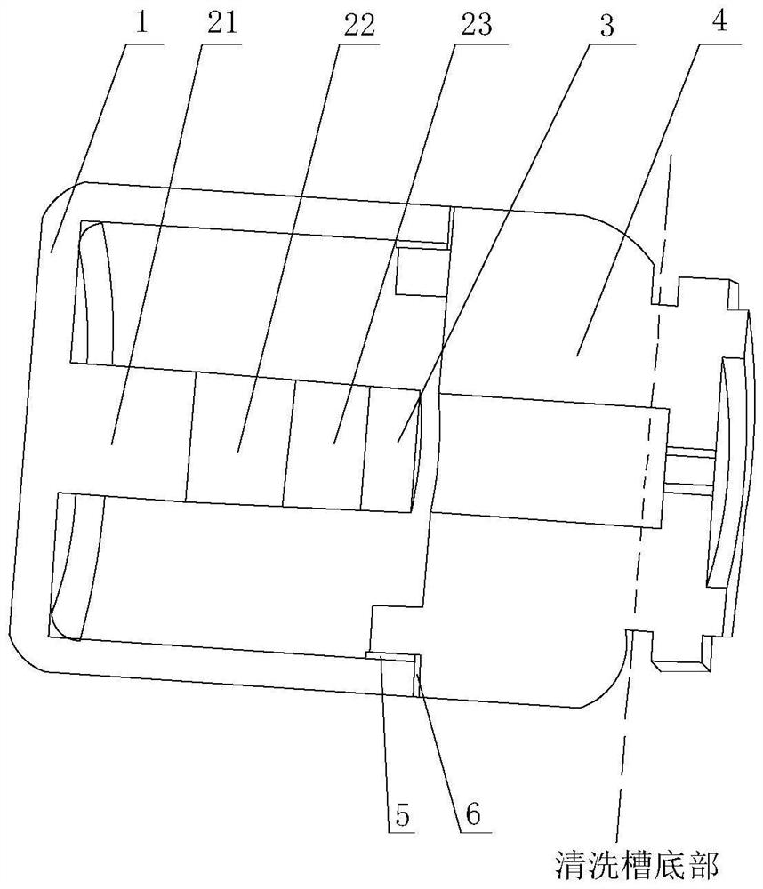
[0031] see figure 1 and figure 2 The ultrasonic transducer with multi-directional vibration provided in this embodiment includes a base 4, a vibrating cover 1 and a vibrating column 2 arranged in the inner cavity of the vibrating cover 1; a sealing vibration isolation layer is arranged between the vibrating cover 1 and the base 4; the vibrating cover 1 is a hollow cylindrical structure, which is inverted on the base 4 and connected with the base 4 to form a closed cavity structure. The top of the vibrating column 2 is connected to the center of the vibrating cover 1, and the vibrating column 2 is excited to generate vibration and transmit it to the vibrating cover 1 , through the vibrating cover 1 radiates a synthetic vibration formed by longitudinal axisymmetric bending vibration and radial transverse vibration alternately.

[0032] In this embodiment, the vibrating cover 1 is a hollow cylindrical structure, and the inner diameter R of the vibrating cover 1 is 15 mm; the de...

Embodiment 2

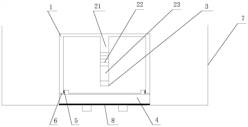
[0046] see figure 2 and image 3 The ultrasonic cleaning device provided in this embodiment includes the ultrasonic transducer and the cleaning tank 7 provided in Embodiment 1; the base 4 of the ultrasonic transducer vibrating in multiple directions is fixed at the bottom center of the cleaning tank 7; The vibrating cover 1 of the ultrasonic transducer vibrating in the direction extends into the cleaning tank 7, through the vibrating cover 1 radiates into the cleaning tank 7 the composite vibration formed by the longitudinal axisymmetric bending vibration and the transverse vibration along the radial direction alternately, so that the cleaning tank 7, a stable radiation sound field composed of transverse vibration and bending vibration is formed.

[0047] In this embodiment, a waterproof gasket 8 is provided at the connection position between the base 4 of the ultrasonic transducer vibrating in multiple directions and the bottom of the cleaning tank 7 . Specifically, the wa...


PUM

PropertyMeasurementUnit
The inside diameter ofaaaaaaaaaa
Depthaaaaaaaaaa

Abstract

The invention belongs to the technical field of transducers, and relates to a multidirectional vibration ultrasonic transducer, an ultrasonic cleaning device and cleaning method. The transducer comprises a base, a vibration cover and a vibration column arranged in an inner cavity of the vibration cover; a sealing vibration isolation layer is arranged between the vibration cover and the base; and the vibration cover is of a hollow cylindrical structure and is inversely arranged on the base to be connected with the base to form a closed cavity structure, the top of the vibration column is connected with the center of the vibration cover, the vibration column is excited to generate vibration which is transmitted to the vibration cover, and the vibration cover radiates composite vibration formed by alternating longitudinal axisymmetric bending vibration and radial transverse vibration. The transducer is simple in structure, small in size, capable of generating composite vibration formed by alternating longitudinal axisymmetric bending vibration and radial transverse vibration, free of cleaning dead angles, high in ultrasonic frequency and good in cleaning effect.

Description

technical field [0001] The invention belongs to the technical field of transducers, and relates to an ultrasonic transducer vibrating in multiple directions, an ultrasonic cleaning device and a cleaning method. Background technique [0002] Piezoelectric transducers are currently the main type of ultrasonic vibration transducers, among which piezoelectric ceramics are mostly used. Since ceramics are easy to process into the required shape, their components and processes can be changed to meet the high performance requirements of various purposes. Therefore, it is widely used; polarized piezoelectric ceramics generate stretching vibration under the excitation of periodic signals, and transmit the vibration through the vibrating rod to realize the conversion of electrical energy and mechanical energy. Most of the existing piezoelectric transducers have a single vibration direction, usually a single vibration, that is, longitudinal vibration or bending vibration. [0003] In t...

Claims


Application Information

Patent Timeline
IPC IPC(8): B08B3/12B08B13/00B06B1/06
CPCB08B3/12B08B13/00B06B1/06
Inventor 贺西平康晓妍
Owner SHAANXI NORMAL UNIV
Why Eureka
Try Eureka