Communication type breakwater wave dissipation structure for resisting wave suction force
A breakwater and wave dissipation technology, which is applied in the direction of breakwaters, jetties, embankments, etc., to achieve the effects of strengthening energy dissipation, improving wave dissipation efficiency, and reducing adverse effects
- Summary
- Abstract
- Description
- Claims
- Application Information
AI Technical Summary
Problems solved by technology
Method used
Image
Examples
Embodiment
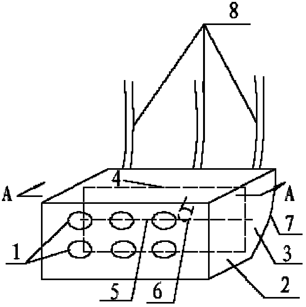
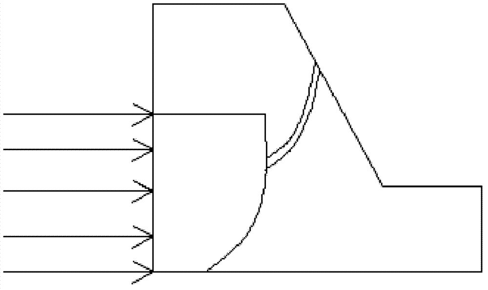
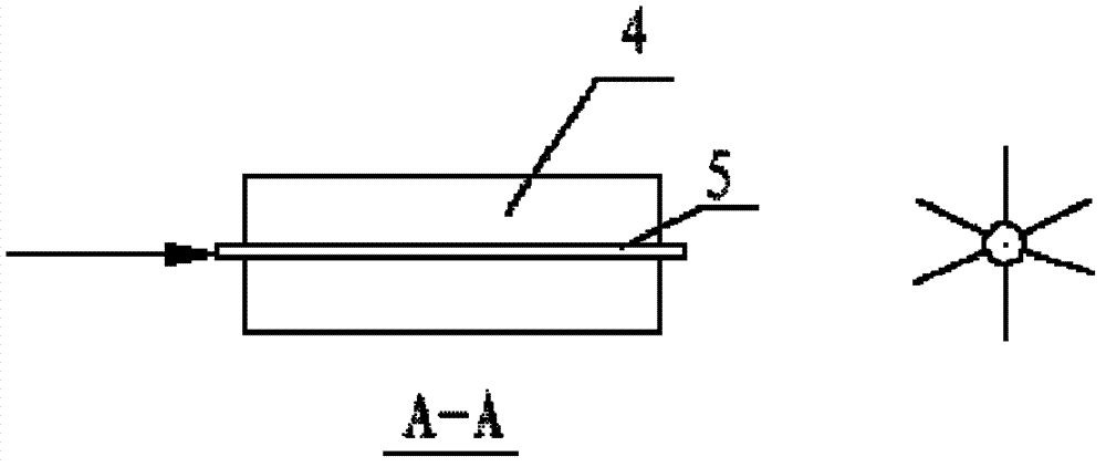
[0039] Such as figure 1 It is known that the wave-dissipating structure is 2m high and 4m long. The front wall of the wave-dissipating empty box 2 is divided into two rows of symmetrically distributed 6 oval-shaped wave-dissipating holes 1, with 3 in the first row and 3 in the second row. The left and right clear distance of wave hole 1 is 1m, the upper and lower clear distance is 0.5m, the long axis is 0.15m, and the short axis is 0.1m. Inside the parapet of the breakwater, the distance between the upper surface of the wave-dissipating structure and the top of the parapet is 1m, the length of the wave-dissipating blade 4 is 1m, and the length of the rotating shaft 5 of the wave-dissipating blade is 4m. The design high water level of the breakwater to be built is 3.5m, and the extreme high water level is 4.39m. The wave height is 2.8m, The wave height is 3.8 m, the design wavelength is 50.50 m, the return period is 50 years, and the water depth in front of the embankment ...
PUM
 Abstract
Description
Claims
Application Information
 - R&D
- Intellectual Property
- Life Sciences
- Materials
- Tech Scout
- Unparalleled Data Quality
- Higher Quality Content
- 60% Fewer Hallucinations
Browse by: Latest US Patents, China's latest patents, Technical Efficacy Thesaurus, Application Domain, Technology Topic, Popular Technical Reports.
© 2025 PatSnap. All rights reserved.Legal|Privacy policy|Modern Slavery Act Transparency Statement|Sitemap|About US| Contact US: help@patsnap.com


