

Newspaper leftover material cutting and recycling device
A technology of scrap cutting and recycling device, which is applied in metal processing and other directions, and can solve the problems of waste of paper resources and other issues
- Summary
- Abstract
- Description
- Claims
- Application Information
AI Technical Summary
Problems solved by technology
Method used
Image

Examples
Embodiment 1
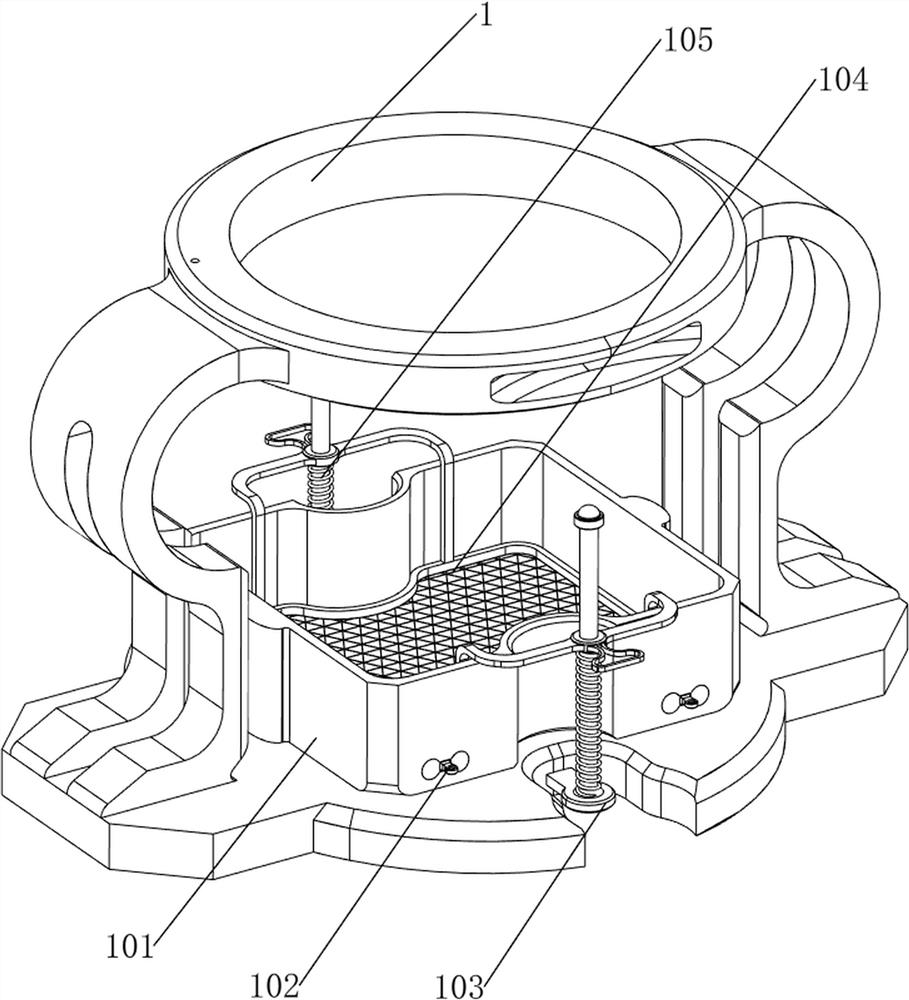
[0030] A kind of newspaper scrap cutting recycling device, such as Figure 1-2 As shown, it includes a first support frame 1, a casing 2, a second support frame 3, a cylinder 4, a knife rest 5, a manual transmission mechanism 6 and a moving mechanism 7, the top of the first support frame 1 is provided with a casing 2, and the top of the casing 2 A second support frame 3 is provided, and a cylinder 4 is provided on the second support frame 3. A tool rest 5 is provided on the telescopic rod of the cylinder 4. A manual transmission mechanism 6 is provided in the middle of the casing 2. Between the manual transmission mechanism and the inner side of the casing 2 Connected with mobile mechanism 7.
[0031] When the user needs to cut newspaper scraps, this device can be used. First, the newspaper to be cut is placed in the manual transmission mechanism 6, and the newspaper is moved to the position directly below the knife holder 5 through the manual movement mechanism 7, and the air...
Embodiment 2
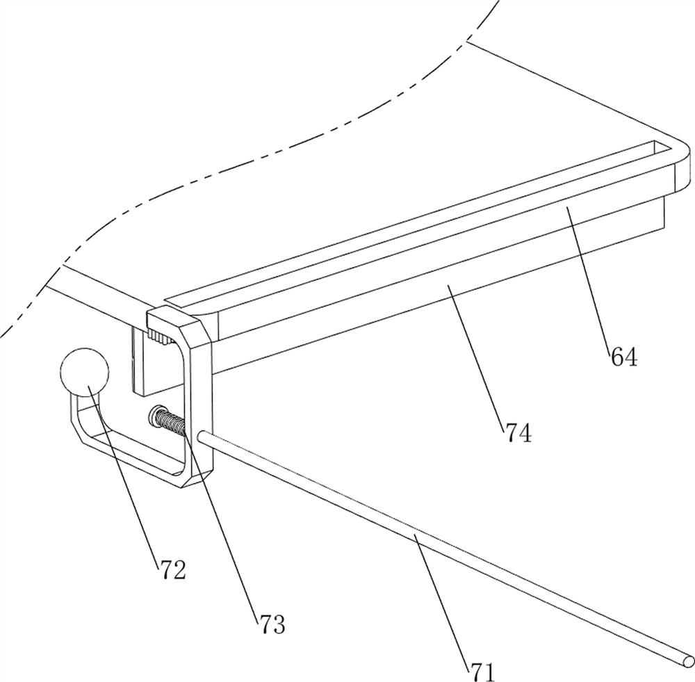
[0033] On the basis of Example 1, such as Figure 1-4 As shown, the manual transmission mechanism 6 includes a fixed frame 61, a first rotating shaft 62, a first flat belt 63 and a fixed frame 64, and the left and right sides of the housing 2 are connected with the fixed frame 61, and the fixed frame 61 rotates between the front and rear sides. The formula is provided with a first rotating shaft 62, a first flat belt 63 is wound around the first rotating shaft 62 through a first pulley, and a plurality of fixing frames 64 are evenly spaced on the first flat belt 63.
[0034] The user can place the newspaper on the fixed frame 64 through the fixed frame 61 on the right side, and then the user can manually rotate the first rotating shaft 62 on one side, and the first rotating shaft 62 on one side rotates to drive the other side through the first flat belt 63. The first rotating shaft 62 on the side rotates, and then the fixed frame 64 moves to the left. When the fixed frame 64 w...
Embodiment 3
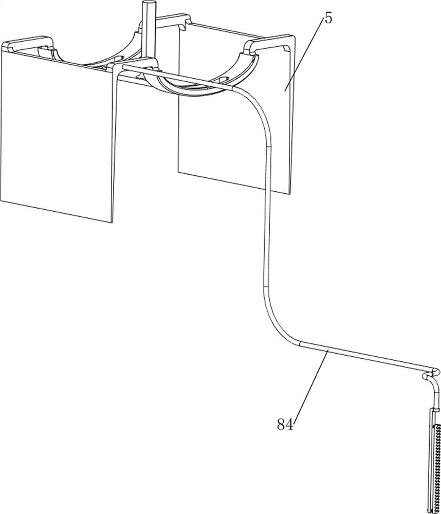
[0038] On the basis of Example 2, such as Figure 1-2 and Figure 5-10 As shown, an automatic transmission mechanism 8 is also included. The automatic transmission mechanism 8 includes a second rotating shaft 81, a second flat belt 82, a ratchet gear 83 and a ratchet rack 84. Two rotating shafts 81, a ratchet gear 83 is arranged on the second rotating shaft 81, a second flat belt 82 is wound between the second rotating shaft 81 and the first rotating shaft 62 on the left side through the second pulley, and the left side of the knife rest 5 is connected with a ratchet Bar 84, the ratchet bar 84 contacts and cooperates with the ratchet gear 83.
[0039]When the tool rest 5 drives the ratchet bar 84 to move downward, the ratchet bar 84 will not drive the ratchet gear 83 to rotate. Make the second rotating shaft 81 rotate, and drive the first rotating shaft 62 on the left side to rotate through the second flat belt 82, so that the first rotating shaft 62 does not need to be manu...
PUM
 Abstract
Description
Claims
Application Information