
High-speed mixing bed adopting spiral fluid director water distribution plate and hexagonal unit perforated plate

A high-speed mixed bed and hexagonal technology, applied in chemical instruments and methods, water/sewage treatment, water/sludge/sewage treatment, etc., can solve the problem of limited hole uniformity, affecting purification efficiency, and poor uniformity of raw water and other problems, so as to avoid excessive local stress, improve the uniformity of water distribution, and achieve the effect of high water distribution uniformity

Active Publication Date: 2021-11-19
国能荥阳热电有限公司 +1
View PDF9 Cites 0 Cited by
  • Summary
  • Abstract
  • Description
  • Claims
  • Application Information

AI Technical Summary

Problems solved by technology

The existing spherical high-speed mixed bed has the following disadvantages: (1) A simple dome-shaped water distribution plate is used to distribute the raw water at the water inlet, which makes the distribution of raw water uneven. The lower part is relatively sparse and the surrounding area is denser, so the porous plate below is prone to deformation due to uneven force, and the raw water flows into the resin layer from the deformed part of the porous plate, which will cause most of the resin to fail, resulting in a reduction in the water production of the spherical high-speed mixed bed; (2) Due to the limited area of ​​the manhole on the high-speed mixed bed, the existing perforated plate is divided into several strip plates, which are handed in from the manhole and then assembled. This long strip structure is due to the area of ​​the middle plate Relatively large, low strength, easy to be impacted and deformed by raw water, and due to the need for butt joints on both sides, water caps cannot be placed at the joints, resulting in limited uniformity of holes, and poor uniformity of raw water after passing through the perforated plate. Purification efficiency

Method used


Image

  • High-speed mixing bed adopting spiral fluid director water distribution plate and hexagonal unit perforated plate
  • High-speed mixing bed adopting spiral fluid director water distribution plate and hexagonal unit perforated plate
  • High-speed mixing bed adopting spiral fluid director water distribution plate and hexagonal unit perforated plate

Examples


Embodiment Construction

[0024] The technical solutions of the present invention will be described in further detail below through specific implementation methods.

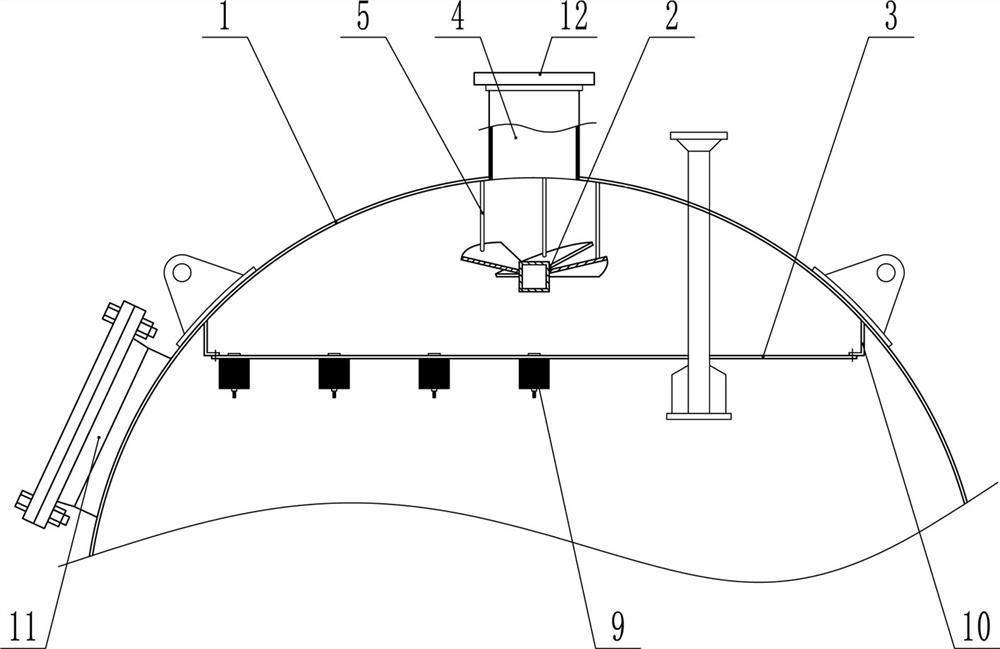
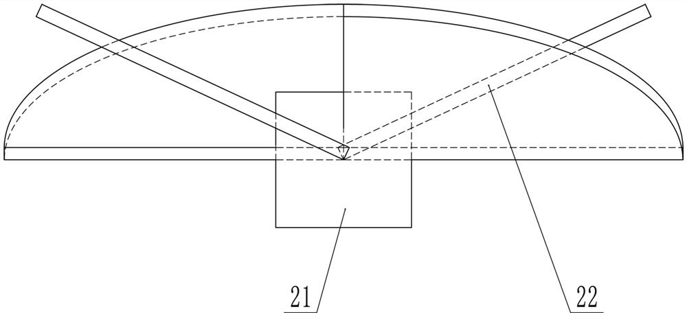
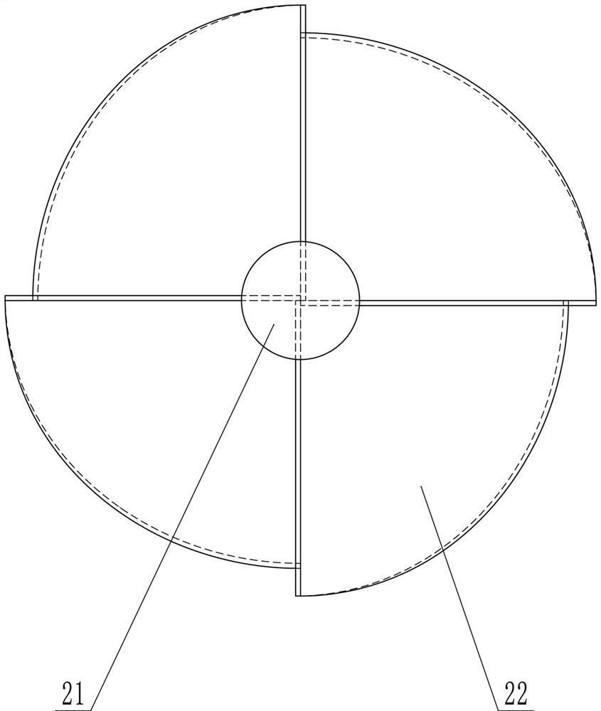
[0025] Such as Figure 1-9 As shown, a high-speed mixed bed adopts a spiral deflector water distribution plate and a hexagonal unit porous plate, including an arc-shaped top shell 1, a fan-shaped water distribution plate 2 and a water distribution porous plate 3. The circular The top of the arc-shaped top shell 1 is provided with a water inlet 4, the fan blade type water distribution plate 2 is arranged directly below the water inlet 4, and the water distribution porous plate 3 is arranged on the fan blade type water distribution plate 2, the blade-type water distribution plate 2 includes a central block 21 and four upturned fan blades 22 evenly connected to the central block 21, and each of the upturned fan blades 22 is Tilting at a certain angle clockwise or counterclockwise, the orthographic projections of the sides of two adjacent up...


PUM


Abstract

The invention provides a high-speed mixing bed adopting a spiral fluid director water distribution plate and a hexagonal unit perforated plate. The high-speed mixing bed comprises an arc-shaped top shell, a fan blade plate type water distribution plate and a water distribution perforated plate, wherein a water inlet is formed in the top end of the arc-shaped top shell, the fan blade plate type water distribution plate is arranged right below the water inlet, the water distribution perforated plate is arranged right below the fan blade plate type water distribution plate, the fan blade plate type water distribution plate comprises a central block and a plurality of upwarp fan blade plates which are uniformly connected to the central block, the water distribution perforated plate comprises a plurality of hexagonal unit plates and a plurality of arc-shaped plates, the hexagonal unit plates are spliced together, and the arc-shaped plates are spliced on the peripheries of the hexagonal unit plates. The high-speed mixing bed adopting the spiral fluid director water distribution plate and the hexagonal unit perforated plate has the advantages of scientific design, high water distribution uniformity, long service life and high purification efficiency.

Description

technical field [0001] The invention relates to a high-speed mixed bed, in particular to a high-speed mixed bed adopting a spiral deflector water distribution plate and a hexagonal unit porous plate. Background technique [0002] The high-speed mixed bed is also called a high-speed ion exchanger. Its principle is to place anion and cation exchange resins in the exchanger, so that the raw water passes through the anion exchange resin to remove anions in the water, and the cation exchange resin to remove cations in the water to obtain pure water. The existing spherical high-speed mixed bed has the following disadvantages: (1) A simple dome-shaped water distribution plate is used to distribute the raw water at the water inlet, which makes the distribution of raw water uneven. The lower part is relatively sparse and the surrounding area is denser, so the porous plate below is prone to deformation due to uneven force, and the raw water flows into the resin layer from the deformed...

Claims


Application Information

Patent Timeline
Patent Type & Authority Applications(China)
IPC IPC(8): C02F1/42
CPCC02F1/42C02F2001/427Y02W10/10
Inventor 张文学祁永胜张高智王永召张志民刘述显常黎陶健芳周南曹侃陈诚李宁张前欣王冠
Owner 国能荥阳热电有限公司
Learn More