
Practical pneumatic barrier gate mechanism

A gate and pneumatic technology, applied in the field of practical pneumatic gate mechanism, can solve the problems of increasing the operating load of the reducer, easy failure, and high noise, and achieve the effects of reducing power requirements, good wind resistance, and low noise.

Pending Publication Date: 2021-11-19
毕梅华
View PDF0 Cites 0 Cited by
  • Summary
  • Abstract
  • Description
  • Claims
  • Application Information

AI Technical Summary

Problems solved by technology

When this kind of barrier is installed in a place with a large crossing span, on the one hand, the aluminum barrier is required to be very long, and the strength of the aluminum barrier is high; on the other hand, when the barrier is raised and lowered, the The power and rotational torque of the motor are required to be large, and the aluminum barrier bar is easy to shake, especially when running in windy weather, the noise caused by the shaking of the aluminum barrier bar is large
[0004] In addition, a power outage will cause the barrier gate to fail. When the barrier gate is driven up and down manually, the overturning of the barrier gate will drive the reducer to operate together, increasing the operating load of the reducer, and it is also prone to failure or damage. The operation can only be carried out after opening the chassis of the gate movement, which is very inconvenient to operate

Method used


Image

  • Practical pneumatic barrier gate mechanism
  • Practical pneumatic barrier gate mechanism
  • Practical pneumatic barrier gate mechanism

Examples


Embodiment Construction

[0041] In order to make the object, technical solution and advantages of the present invention clearer, the present invention will be further described in detail below in conjunction with the accompanying drawings.

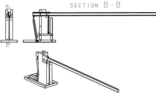
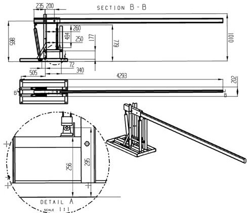
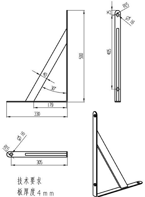
[0042] like Figure 18 As shown, the present invention provides a practical pneumatic barrier mechanism; figure 1 and figure 2 , one end of the aluminum barrier rod 5 is connected to the riser assembly 2 through the end face bearing 7; The fixed angle steel of the cylinder on the 2 is connected by screws, and the piston end is connected with the aluminum barrier rod 5 for driving the aluminum barrier rod 5 to turn over.

[0043]The first is the balance of the aluminum barrier bar 5. The right end of the aluminum barrier bar 5 protrudes 4 meters, nearly 5 kilograms per meter, and a total of nearly 20 kilograms. Its center of gravity is at a place of 2 meters, so it The moment arm is nearly 2 meters * 40 kg = 80 kilogram meters, that is, the balance of the left ...


PUM

PropertyMeasurementUnit
Thicknessaaaaaaaaaa
Outer diameteraaaaaaaaaa
The inside diameter ofaaaaaaaaaa

Abstract

The invention discloses a practical pneumatic barrier gate mechanism. The practical pneumatic barrier gate mechanism comprises an air cylinder, a Y-shaped connector, an I-shaped connector, a single-lug base, a double-lug base, a tension spring fixing groove assembly, a tension spring, an opening hook, an aluminum barrier gate rod, a gate rod steel sleeve, an end face bearing, air cylinder fixing angle steel, an air cylinder, a triangular fixing frame, a bottom plate, a vertical plate assembly, a lower air pipe, an upper air pipe, an oil-water separator, an air compressor air storage tank and a steel plate shell. One end of the aluminum barrier gate rod is connected with the vertical plate assembly through an end face bearing, a shaft, a nut and the like. The driving air cylinder is vertically placed, the bottom of the driving air cylinder is a fixed end, the top of the driving air cylinder is a piston end, the fixed end is connected with the air cylinder fixing angle steel on the vertical plate assembly through screws, and the piston end is connected with the aluminum barrier gate rod and used for driving the aluminum barrier gate rod to turn over. The mechanism has the advantages that the end face bearing enables the aluminum barrier gate rod to be good in wind resistance; noise in the rising and falling process is low through the air cylinder; power can be provided by the air storage tank during power failure; the use of the tension spring reduces the power requirement of the air cylinder, and more energy is saved.

Description

technical field [0001] The invention relates to the technical field of barrier gate equipment, in particular to a practical pneumatic barrier gate mechanism. Background technique [0002] Barrier gates, also known as car stoppers, are passageway entrance and exit management equipment used to restrict motor vehicles on the road. They are now widely used in road tolls, community gates, factories, school gates, etc. [0003] At present, the lift of the barrier gate is generally driven by a motor. When this kind of barrier is installed in a place with a large crossing span, on the one hand, the aluminum barrier is required to be very long, and the strength of the aluminum barrier is high; on the other hand, when the barrier is raised and lowered, the The power and rotational torque of the motor are required to be large, and the aluminum barrier bar is easy to shake, especially when it is running in windy weather, the noise caused by the shaking of the aluminum barrier bar is la...

Claims


Application Information

Patent Timeline
IPC IPC(8): E01F13/06
CPCE01F13/06
Inventor 潘成陈茗李春涛余娇夏敏殷朱夕青邱星耀
Owner 毕梅华
Learn More