
Fiber grating displacement sensor

A technology of displacement sensor and optical fiber grating, which is applied in the field of sensors, can solve the problems of easy fracture damage, poor applicability, vertical displacement, etc., and achieve the effects of wide application range, low cost and improved measurement accuracy

Inactive Publication Date: 2021-11-19
SHANGHAI DIANJI UNIV
View PDF0 Cites 0 Cited by
  • Summary
  • Abstract
  • Description
  • Claims
  • Application Information

AI Technical Summary

Problems solved by technology

The tensile method is to directly fix one end of the fiber grating to the moving object to be measured, which has high precision but a small range, and is prone to fracture and damage; the shrapnel method converts the deformation of the shrapnel into grating strain, and the structure has a small range and poor applicability; the cantilever beam structure is Use the grating wavelength on the upper and lower surfaces of the cantilever beam to achieve temperature compensation, but the structure is prone to vertical displacement

Method used


Image

  • Fiber grating displacement sensor
  • Fiber grating displacement sensor

Examples


Embodiment Construction

[0028] Attached below Figure 1-2 The present invention is further illustrated with specific examples.

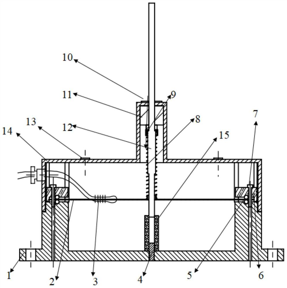
[0029] Such as figure 1 As shown, a fiber grating displacement sensor, including:

[0030] The shell, the shell is divided into a base 1 and a top cover 14, the base 1 is a hollow structure and has an opening at one end, and the top cover 14 detachably encapsulates the opening of the base 1;

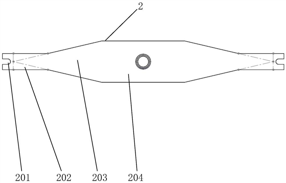
[0031] An elastic element 2 made of elastic material, the two ends of the elastic element 2 are installed on the base 1;

[0032] An axially arranged and slidable displacement measuring rod 12, the displacement measuring rod 12 axially passes through the top cover 14, a part of the displacement measuring rod 12 is in the inner cavity of the housing and passes through the middle part of the elastic element 2, and the other part extends out of the housing and rigging moving or deforming objects;

[0033] Spring 8, the spring 8 is set on the displacement measuring rod 12 and is in th...


PUM


Abstract

The invention discloses a fiber grating displacement sensor. The sensor comprises a housing which is divided into a pedestal and a top cover, an elastic element with two ends mounted on the pedestal, a displacement measuring rod axially arranged and capable of sliding, a spring and a fiber bragg grating; the displacement measuring rod is axially connected with the top cover in a penetrating manner, one part of the displacement measuring rod is located in the inner cavity of the shell and penetrates through the middle part of the elastic element, and the other part of the displacement measuring rod extends out of the shell and is assembled with a moving object or a deformed object; the spring sleeves the displacement measuring rod and is located in the inner cavity of the shell, the lower end of the spring is connected with the middle part of the elastic element, the upper end of the spring is connected with the displacement measuring rod, and the spring is located above the elastic element; and the fiber bragg grating is bonded on the elastic element and generates tension and compression deformation along with the deformation of the elastic element. All the functions are easy and convenient to achieve, no complex mechanism part exists, manufacturing cost is low, cost is low, and the application range is wide.

Description

technical field [0001] The invention relates to the technical field of sensors, in particular to a displacement monitoring sensor for the fields of general machinery, civil engineering, aerospace and water conservancy facilities and the like. Background technique [0002] Compared with traditional sensors, fiber grating sensors have the advantages of high precision, small size, and light weight. However, fiber gratings are brittle and cannot be directly used to measure physical signals such as displacement and temperature. Package design is required to facilitate measurement of different physical signal. Although there have been some research results on fiber grating displacement sensors, the measurement effect needs to be further improved, especially in terms of measurement accuracy, range and response time. It is necessary to develop a fiber grating displacement sensor with high precision, fast response and large range. [0003] There are many types of fiber grating displ...

Claims


Application Information

Patent Timeline
IPC IPC(8): G01B11/02
CPCG01B11/02
Inventor 吴入军杨雯
Owner SHANGHAI DIANJI UNIV
Learn More