Multi-point linkage photovoltaic power generation tracking support
A photovoltaic power generation, multi-point linkage technology, applied in photovoltaic power generation, photovoltaic module support structure, photovoltaic module and other directions, can solve the problem of high material cost, achieve the effect of reasonable structure design, reduce spindle torque, and improve strength
- Summary
- Abstract
- Description
- Claims
- Application Information
AI Technical Summary
Problems solved by technology
Method used
Image

Examples
Embodiment 1
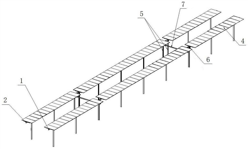
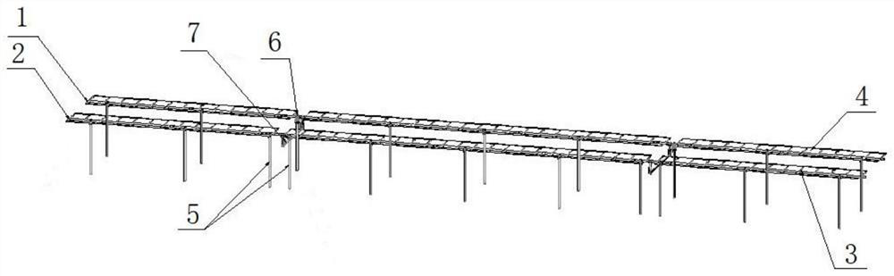
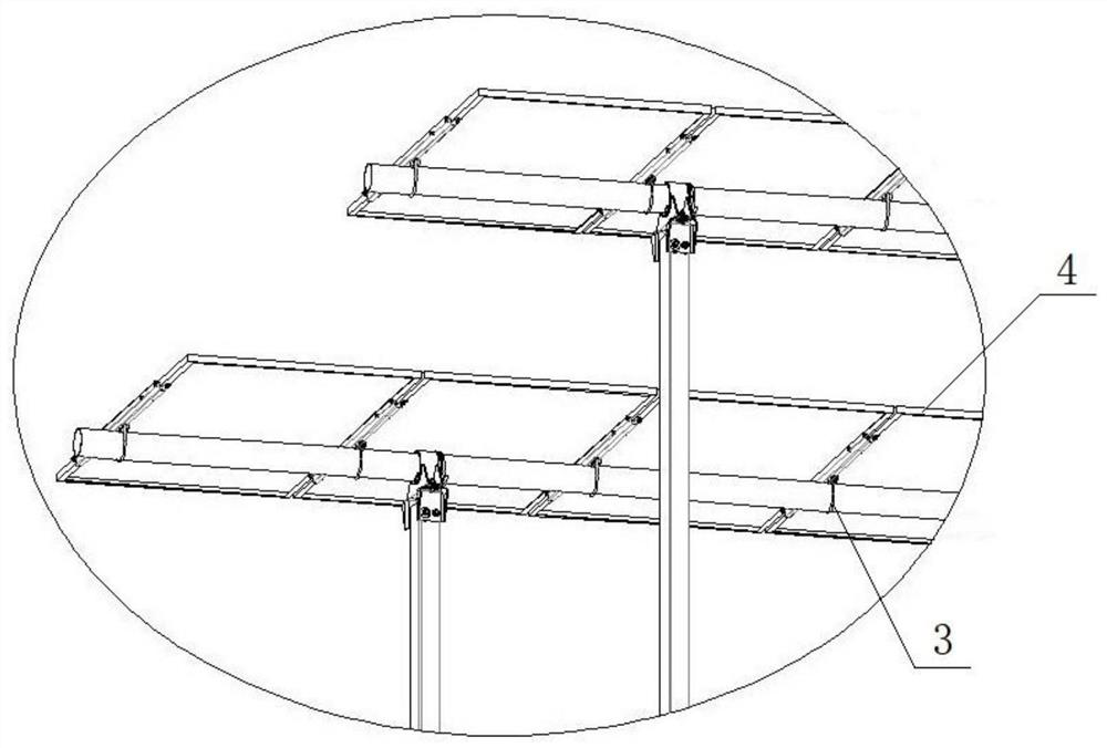
[0030] Such as Figure 1-Figure 6 As shown, this embodiment is a multi-point linkage photovoltaic power generation tracking support, including at least two main shafts arranged side by side, and a plurality of columns 5 for supporting the main shafts. The main shafts are used to fix solar panels 4, and one of the main shafts is As drive shaft 1, the other main shaft acts as driven shaft 2. A rotary speed reducer 6 for driving the rotation of the drive shaft 1 is installed, and a mechanical transmission mechanism 7 is installed between the drive shaft 1 and the driven shaft 2 .
[0031] In this embodiment, the mechanical transmission mechanism 7 includes a connecting sleeve 71, a standpipe 72, a connecting groove plate 73, a horizontal tube 74, and a positioning shaft 75. The two ends of the horizontal tube 74 are respectively provided with a positioning shaft 75, and the outside of the positioning shaft 75 Two connection groove plates 73 are fixed symmetrically at the ends, a...
Embodiment 2
[0038] The structure and application of this embodiment are basically the same as those of Embodiment 1, the difference is that there are three main shafts, of which the main shaft is used as the driving shaft 1, the other two main shafts are used as the driven shaft 2, and the two driven shafts 2 are distributed on both sides of the drive shaft 1, and a mechanical transmission mechanism 7 is installed between the drive shaft 1 and each driven shaft 2, and the positions of the mechanical transmission mechanisms 7 are staggered from each other.
Embodiment 3
[0040] The structure and application of this embodiment are basically the same as those of Embodiment 1, the difference is that there are three main shafts, of which the main shaft is used as the driving shaft 1, the other two main shafts are used as the driven shaft 2, and the two driven shafts 2 Distributed on the same side of the drive shaft 1, a mechanical transmission mechanism 7 is installed between the drive shaft 1 and the adjacent driven shaft 2, and between two driven shafts 2, and the positions of the mechanical transmission mechanisms 7 are staggered from each other .
PUM
 Abstract
Description
Claims
Application Information
 - R&D Engineer
- R&D Manager
- IP Professional
- Industry Leading Data Capabilities
- Powerful AI technology
- Patent DNA Extraction
Browse by: Latest US Patents, China's latest patents, Technical Efficacy Thesaurus, Application Domain, Technology Topic.
© 2024 PatSnap. All rights reserved.Legal|Privacy policy|Modern Slavery Act Transparency Statement|Sitemap