
BTO intelligent correction device and method of full-automatic lead bonding machine

A technology of wire bonding machine and calibration method, which is applied to non-electric welding equipment, electrical components, circuits, etc., can solve the problems of manual operation and measurement workload, easy to make mistakes, etc., to achieve high calibration efficiency and reliability, and fast calibration speed. , The effect of improving the yield rate

Active Publication Date: 2021-11-23
NINGBO SHANGJIN AUTOMATION TECH CO LTD
View PDF10 Cites 4 Cited by
  • Summary
  • Abstract
  • Description
  • Claims
  • Application Information

AI Technical Summary

Problems solved by technology

Replacing the riving knife also requires re-measurement
In addition, for fully automatic wire bonding machines, when the hacking knife is rotated to different angles, the BTO will be different due to the machining accuracy and installation accuracy of the parts, which requires frequent recalibration of the BTO and measurement of different BTOs at different angles, manual operation Measurements are heavy and error-prone

Method used


Image

  • BTO intelligent correction device and method of full-automatic lead bonding machine
  • BTO intelligent correction device and method of full-automatic lead bonding machine

Examples


Embodiment Construction

[0031] Now in conjunction with accompanying drawing, the present invention will be further described:

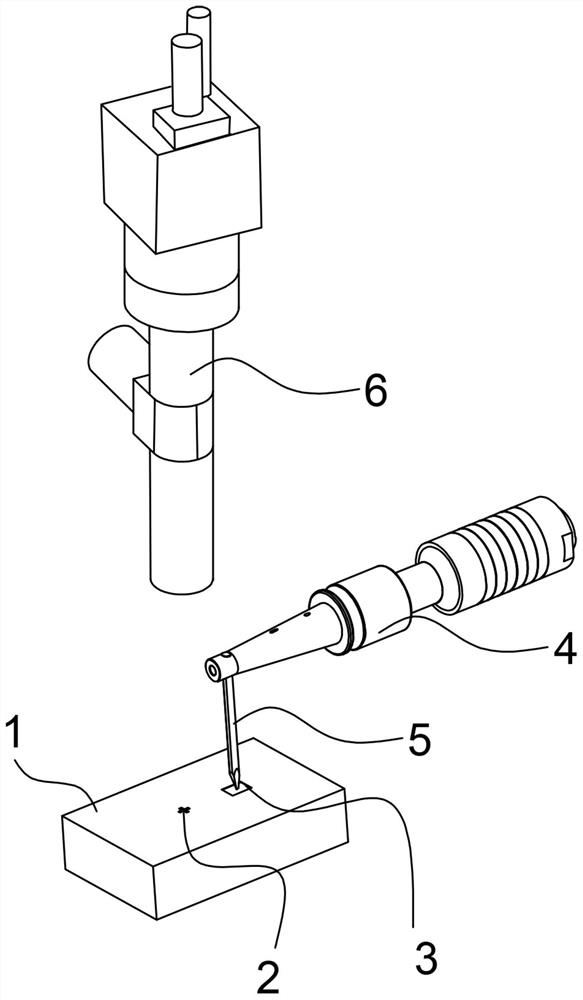
[0032] refer to figure 1 , a BTO intelligent correction device of a fully automatic wire bonding machine described in this embodiment, the fully automatic wire bonding machine includes a workbench 1 for carrying chip workpieces, a bonding head 4 provided with a chopper 5 and imaging optical system 6 .

[0033] The BTO intelligent correction device includes:

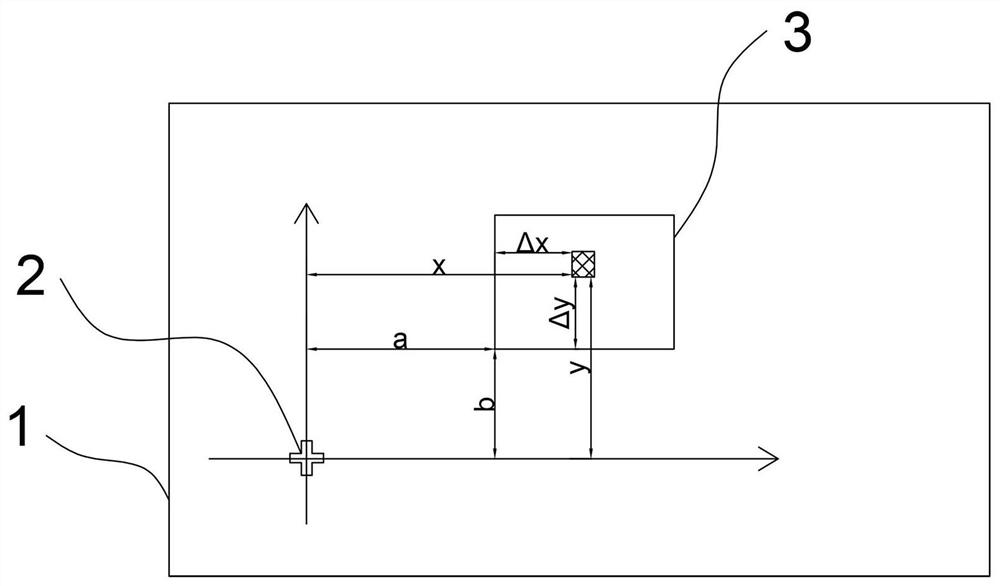
[0034] The basic mark point 2 is set on the workbench 1 for alignment and recognition by the imaging optical system 6 as the origin of the plane coordinate system;

[0035] The detector 3 is arranged on the workbench 1 at a theoretical BTO position away from the basic marking point 2, and is used to detect the distance between it and the riving knife 5 and generate an electrical signal by induction when the riving knife 5 moves to the adjacent position above the detector 3;

[0036] The difference correction system i...


PUM


Abstract

The invention relates to a BTO intelligent correction device and method of a full-automatic lead bonding machine. The full-automatic lead bonding machine comprises a workbench for bearing a chip workpiece, a bonding head provided with a chopper, and an imaging optical system. The BTO intelligent correction device comprises a basic mark point, a detector and a difference value correction system, wherein the basic mark point is arranged on the workbench and used for being aligned and identified by the imaging optical system to serve as an original point of a plane coordinate system; the detector is arranged at a theoretical BTO position, away from the basic mark point, on the workbench and used for detecting the distance between the detector and the chopper and generating an electric signal through induction when the chopper moves to an adjacent position above the detector; and the difference value correction system is used for pre-storing theoretical position coordinates when the chopper is induced, calculating a difference value between actual position coordinates and the theoretical position coordinates when the chopper is induced, obtained by the imaging optical system, and obtaining a BTO deviation value for performing compensation correction. The device is simple and small in structure, no extra equipment is added, the BTO deviation can be automatically corrected in real time, and the bonding precision of the chopper is improved.

Description

technical field [0001] The invention relates to the technical field of wire bonding machines, in particular to a BTO intelligent correction device and method for a fully automatic wire bonding machine. Background technique [0002] A fully automatic wire bonding machine is a device that uses ultrasonic waves, heat and pressure to electrically connect metal wires to semiconductor chips and pins. It uses a transducer and a rivet to apply ultrasonic vibrations to the bonding point to form a bond on the chip or pin that is in contact with the wire, thereby achieving a strong electrical connection. By adjusting different process parameters such as pressure, ultrasonic energy and device heating temperature, the required bonding effect can be achieved. The bonding head is installed on the XY motion platform, and the bonding area is determined by the stroke of the XY motion platform. Due to the directional nature of wire bonding, the bond head needs to be rotated to complete the b...

Claims


Application Information

Patent Timeline
Patent Type & Authority Applications(China)
IPC IPC(8): B23K20/10B23K20/26H01L21/607
CPCB23K20/10B23K20/26H01L24/78H01L2224/78001H01L2224/787H01L2224/78753H01L2224/78313
Inventor 陈文赵冰
Owner NINGBO SHANGJIN AUTOMATION TECH CO LTD
Learn More