Forming injection mold and injection molding method thereof

An injection mold and mold technology, applied in the field of molding injection molds and injection molding, can solve the problems of clogging the mouth of the nozzle, unable to ensure the uniform distribution of liquid, and accelerate the cooling of liquid, so as to avoid the operation of pushing and discharging, avoid The effect of uneven distribution of injection liquid and reduction of secondary operations

Pending Publication Date: 2021-11-23
昆山达菲乐电子产品有限公司
View PDF5 Cites 0 Cited by
  • Summary
  • Abstract
  • Description
  • Claims
  • Application Information

AI Technical Summary

Problems solved by technology

[0003] However, there are some problems in the existing ones. Most of the existing molding injection molding operations require injection molding and mold taking; and then prepare for the next injection molding; but most of the existing molding injection molding adopts a separate method, separating the injection molding part and the mold clamping part. , to achieve independent operation; in the actual production process, the increase in the path of the injection molding part and the mold clamping part will not only accelerate the cooling of the liquid; , so in the case of small parts, the uniform distribution of liquid in each cavity cannot be guaranteed; in addition, traditional ejection needs to be done on the same side, thus limiting the operating range

Method used


Image

  • Forming injection mold and injection molding method thereof
  • Forming injection mold and injection molding method thereof
  • Forming injection mold and injection molding method thereof

Examples


Embodiment Construction

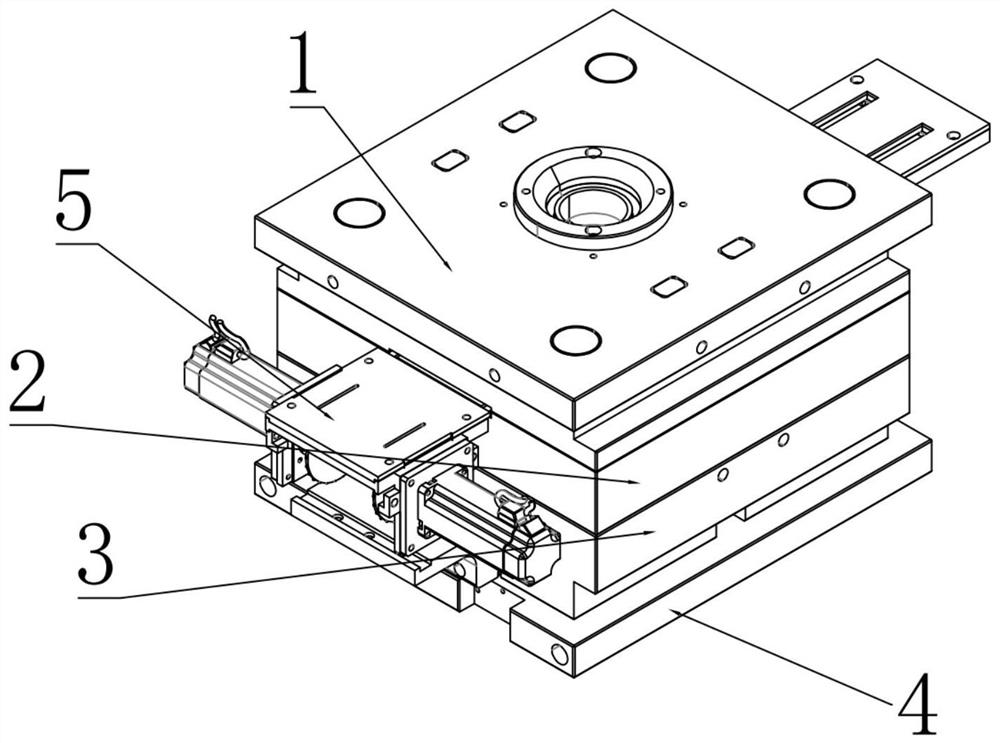
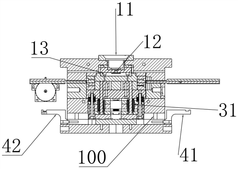
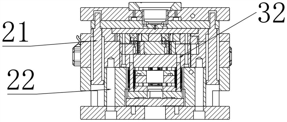
[0029] A molding injection mold, comprising: an injection plate 1, an upper mold 2, a lower mold 3, a bottom plate 4, a driving assembly 5, a liquid injection hole 11, a nozzle opening 12, a through hole 13, a limit pin 21, a limit groove 22, Spring 31 , spring support 32 , second fixed block 41 , first fixed block 42 , first motor 51 , pin shaft 100 , mold ejection bracket 110 .

[0030] Injection template 1, the upper mold 2 that is arranged on described injection template 1 below, the lower mold 3 that is arranged on described upper mold 2 below; The bottom plate 4 that is arranged on described lower mold 3; And is arranged on described injection template 1 and The driving assembly 5 at the matching place of the upper mold 2; the injection plate 1, the upper mold 2 and the lower mold 3 are fixed by a limit pin 21; and the limit pin 21 can move up and down; avoid mold injection There is a positional shift.

[0031] The injection plate 1 includes a liquid injection hole 11 a...


PUM


Abstract

The invention discloses a forming injection mold and an injection molding method thereof. The forming injection mold comprises an injection molding plate, an upper mold arranged below the injection molding plate, a lower mold arranged below the upper mold, a bottom plate arranged on the lower mold and a driving assembly arranged at the cooperation position of the injection molding plate and the upper mold; then the injection molding plate is placed on the upper mold; then an injection molding portion and a mold closing portion are combined, and blockage caused by long-time retention of injection molding liquid to a nozzle opening is reduced; meanwhile, a vertical forming injection molding processing mode is adopted so that molds with different specifications can receive uniform injection molding liquid; and injection molding liquid in a mold groove is prevented from being distributed unevenly during transverse machining, the forming mold is subjected to automatic demolding through springs while the injection molding plate is jacked up by limiting pins, in addition, the material pushing speed and distance of the mold after demolding are set according to the driving assembly, and damage to different injection molding materials is avoided.

Description

technical field [0001] The invention relates to an injection molding device, in particular to a molding injection mold and an injection molding method thereof. Background technique [0002] Injection molding, also known as injection molding, is a molding method of injection and molding; at a certain temperature, the completely molten plastic material is stirred by a screw, injected into the mold cavity with high pressure, and after cooling and solidification, a molded product is obtained. . [0003] However, there are some problems in the existing ones. Most of the existing molding injection molding operations require injection molding and mold taking; and then prepare for the next injection molding; but most of the existing molding injection molding adopts a separate method, separating the injection molding part and the mold clamping part. , to achieve independent operation; in the actual production process, the increase in the path of the injection molding part and the mo...

Claims


Application Information

Patent Timeline
Patent Type & Authority Applications(China)
IPC IPC(8): B29C45/27B29C45/33B29C45/38B29C45/40
CPCB29C45/27B29C45/332B29C45/38B29C45/40
Inventor 王振
Owner 昆山达菲乐电子产品有限公司
Why Eureka
Try Eureka