
Rotary positioning device

A positioning device and mounting frame technology, which is applied in the direction of transportation and packaging, conveyor objects, etc., can solve the problems of long movement, slow cylinder speed, short life, etc., and achieve fast rotation positioning, less space occupation, and high positioning accuracy. Effect

Pending Publication Date: 2021-11-23
ZHEJIANG CHINT ELECTRIC CO LTD
View PDF0 Cites 0 Cited by
  • Summary
  • Abstract
  • Description
  • Claims
  • Application Information

AI Technical Summary

Problems solved by technology

However, due to the large size of the rotary cylinder and the gripper cylinder, the movement of the product is relatively long, and each cylinder also has defects such as slow speed, poor positioning accuracy and short life, so in actual production , the above-mentioned automation equipment is increasingly unable to meet the functional requirements of the product's rapid rotation and positioning

Method used


Image

  • Rotary positioning device
  • Rotary positioning device

Examples


Embodiment Construction

[0029] The technical solutions of the present invention will be clearly and completely described below in conjunction with the accompanying drawings. Apparently, the described embodiments are some of the embodiments of the present invention, but not all of them. Based on the embodiments of the present invention, all other embodiments obtained by persons of ordinary skill in the art without making creative efforts belong to the protection scope of the present invention.

[0030] In the description of the present invention, it should be noted that the terms "center", "upper", "lower", "left", "right", "vertical", "horizontal", "inner", "outer" etc. The indicated orientation or positional relationship is based on the orientation or positional relationship shown in the drawings, and is only for the convenience of describing the present invention and simplifying the description, rather than indicating or implying that the referred device or element must have a specific orientation, ...


PUM


Abstract

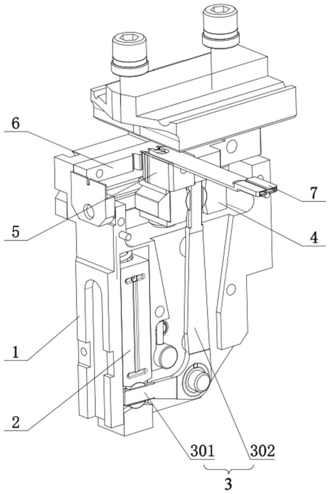
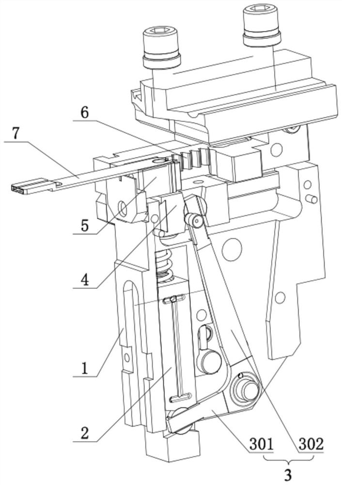
The invention discloses a rotary positioning device, and belongs to the technical field of automatic equipment. The rotary positioning device comprises a shell, a linear output mechanism, a connecting rod mechanism, a sliding block, a gear, a rack and a conveying clamp; the output end of the linear output mechanism can reciprocate along a first straight line; the connecting rod mechanism can rotate around a first axis, the free end of a first rod of the connecting rod mechanism is rotationally connected to the output end of the linear output mechanism, the sliding block can reciprocate along a second straight line, the free end of a second rod is rotationally connected to the sliding block, the gear is rotationally connected to the sliding block and can rotate around a second axis, and the rack is meshed with the gear; one end of the conveying clamp is fixedly arranged on the gear, and the other end of the conveying clamp is used for clamping products; and the conveying clamp can synchronously rotate and move along with the gear in a first plane. According to the rotary positioning device, one-way linear motion can be converted into rotary motion and linear motion, the structure is compact, the occupied space is small, and rapid rotary positioning of a product can be achieved.

Description

technical field [0001] The invention relates to the technical field of automation equipment, in particular to a rotary positioning device. Background technique [0002] There are a lot of automation equipments that realize product rotation positioning. The automation equipment usually adopts the mechanical form of rotary cylinder and jaw cylinder linkage to realize the clamping and rotation positioning of products. However, due to the large size of the rotary cylinder and the gripper cylinder, the movement of the product is relatively long, and each cylinder also has defects such as slow speed, poor positioning accuracy and short life, so in actual production , the above-mentioned automation equipment is increasingly unable to meet the functional requirements of rapid rotation and positioning of products. [0003] Therefore, how to propose a rotary positioning device that has a compact structure, a small size, and can realize rapid rotary positioning of products is a techni...

Claims


Application Information

Patent Timeline
Patent Type & Authority Applications(China)
IPC IPC(8): B65G47/90B65G47/244
CPCB65G47/902B65G47/90B65G47/244
Inventor 李俐高玉保黄旗忠
Owner ZHEJIANG CHINT ELECTRIC CO LTD
Learn More