Low-voltage anode foil corrosion device for electrolytic capacitor
A low-voltage anode foil and electrolytic capacitor technology, applied in the electrolytic process, electrolytic components, etc., can solve the problems that the foil cannot be corroded, the effect is not ideal, and the foil cannot enter the tank liquid regularly and quantitatively. speed, improve processing efficiency, and smooth the processing cycle.
- Summary
- Abstract
- Description
- Claims
- Application Information
AI Technical Summary
Problems solved by technology
Method used
Image

Examples
Embodiment 1
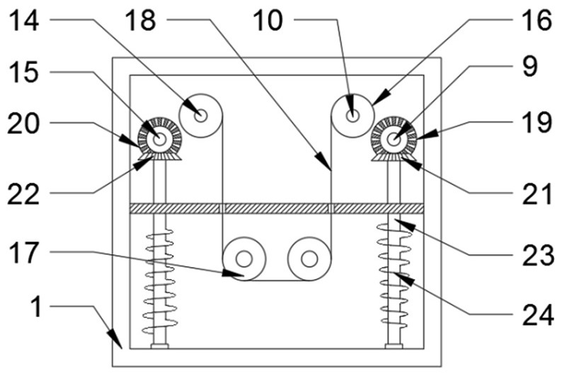
[0027] Such as Figure 1-2 As shown, in the embodiment of the present invention, a low-voltage anode foil corrosion device for electrolytic capacitors, the low-voltage anode foil corrosion device for electrolytic capacitors includes:
[0028] Corrosion box 1, the inside of the corrosion box 1 is rotatably connected with a stirring mechanism, which is used to prevent the bottom of the corrosion box 1 from forming sediment;
[0029] Transmission mechanism one, the transmission mechanism one is rotationally connected with the stirring mechanism, and is used to drive the stirring mechanism to rotate inside the corrosion box 1;
[0030] a feeding mechanism, the feeding mechanism is rotatably connected to the inside of the corrosion box 1, and is used to transport the foil 18 to be processed; and
[0031] Transmission mechanism 2, the transmission mechanism 2 is connected to the transmission mechanism 1 in rotation, and is used to drive the feeding mechanism to rotate inside the co...
Embodiment 2
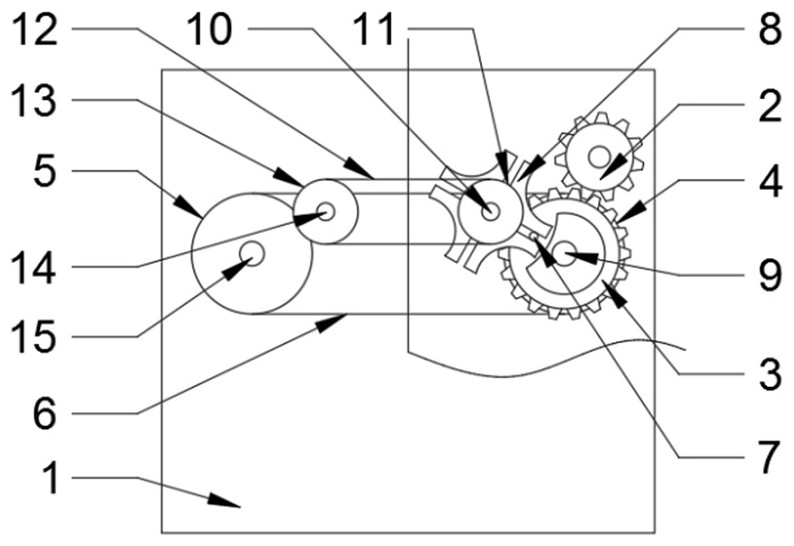
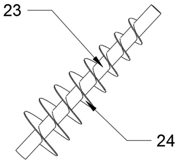
[0034] Such as image 3 As shown, in the embodiment of the present invention, the present invention also provides another embodiment, the difference between this embodiment and the above-mentioned embodiment is: the diameter of a single helical blade in the stirring blade 24 is from one end of the stirring shaft 23 to The other end increases sequentially, which can improve the stirring efficiency of the stirring blade 24 when rotating, and improve the anti-sedimentation effect inside the corrosion tank 1 .
[0035] The working principle of the present invention is:
[0036] In this embodiment, when it is necessary to electrolytically process the foil 18 inside the corrosion box 1, in order to avoid precipitation at the bottom of the corrosion box 1 and affect the electrolysis effect of the foil 18, the rotation of the driving gear 2 can further drive and mesh with it. The driven gear 3 rotates, and the driven gear 3 further drives the driven pulley one 4 to rotate, and the dr...
PUM
 Abstract
Description
Claims
Application Information
 - R&D
- Intellectual Property
- Life Sciences
- Materials
- Tech Scout
- Unparalleled Data Quality
- Higher Quality Content
- 60% Fewer Hallucinations
Browse by: Latest US Patents, China's latest patents, Technical Efficacy Thesaurus, Application Domain, Technology Topic, Popular Technical Reports.
© 2025 PatSnap. All rights reserved.Legal|Privacy policy|Modern Slavery Act Transparency Statement|Sitemap|About US| Contact US: help@patsnap.com