
Industrial sewage recovery treatment equipment

A technology for recovery and treatment of industrial sewage, applied in water/sewage treatment equipment, water/sewage treatment, water/sewage multi-stage treatment, etc., to achieve the effect of increasing the electrolysis rate and increasing the aeration effect

Inactive Publication Date: 2021-06-01
泉州早稻云信息科技有限公司
View PDF0 Cites 0 Cited by
  • Summary
  • Abstract
  • Description
  • Claims
  • Application Information

AI Technical Summary

Problems solved by technology

[0004] Aiming at the deficiencies in the prior art, the purpose of the present invention is to provide a kind of industrial sewage recovery treatment equipment to solve the existing problems

Method used


Image

  • Industrial sewage recovery treatment equipment
  • Industrial sewage recovery treatment equipment
  • Industrial sewage recovery treatment equipment

Examples


no. 1 example

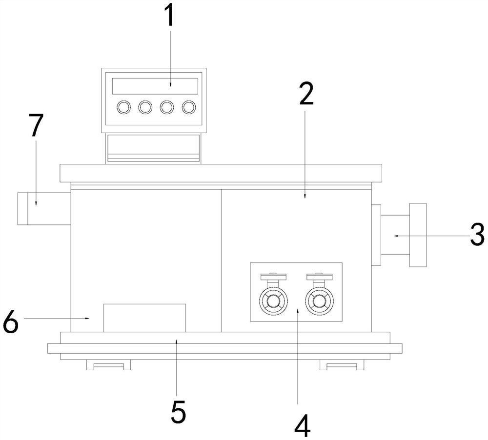
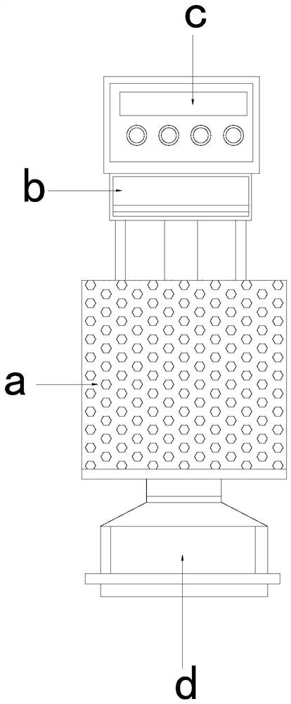
[0026] see Figure 1-Figure 3 , the present invention provides a technical solution for industrial sewage recovery and treatment equipment: its structure includes: an electrolytic frame body 1, a sedimentation tank 2, a water outlet pipe 3, a sewage pipe 4, a support base 5, a purification tank 6, and a water inlet pipe 7. The water pipe 3 is installed in the sedimentation tank 2 on the right side of the sedimentation tank 2 and is buckled. The front side of the sedimentation tank 2 is provided with a sewage pipe 4, and the left side of the sedimentation tank 2 is provided with a purification tank 6. Buckle connection, the support base 5 is provided under the purification tank 6, the electrolysis rack body 1 is arranged above the purification tank 6, the electrolysis rack body 1 is buckled with the purification tank 6, and the upper left side of the purification tank 6 is provided with The water inlet pipe 7, the electrolysis frame body 1 includes the reactor device a, the ele...

no. 2 example

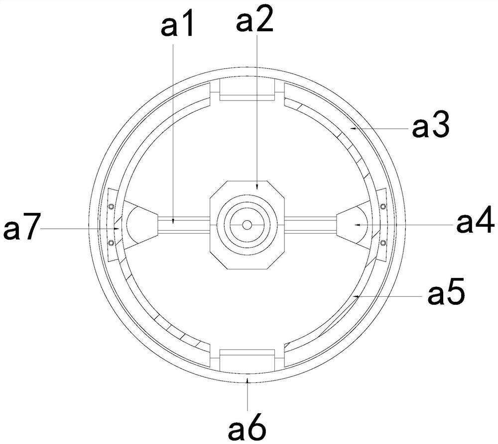
[0030] see Figure 4-Figure 6 , the present invention provides a technical solution for industrial sewage recovery and treatment equipment: its structure includes: the aeration auxiliary frame a1 includes an aeration strip a11, a linkage rod a12, a sleeve frame a13, and a loading groove a14, and the aeration strip a11 Set on the inner side of the sleeve frame a13 and fastened with the sleeve frame a13, the inner end of the sleeve frame a13 is provided with a linkage rod a12, the linkage rod a12 is locked with the sleeve frame a13, and the outer end of the sleeve frame a13 is welded with a loading recess Slot a14.

[0031] The aeration bar a11 includes a grille bushing a111 and a support inner rod a112. The grille bushing a111 is sleeved on the outer side of the support inner rod a112 and buckled with the support inner rod a112.

[0032] The scraper device a4 includes an assembly vertical plate a41, a fitting scraper a42, and a connection groove a43. An assembly riser a41 is ...


PUM


Abstract

The invention discloses industrial sewage recovery treatment equipment which structurally comprises an electrolysis frame machine body, a sedimentation tank, a water outlet pipe, a sewage discharge pipe, a supporting base, a purification tank and a water inlet pipe. When the eqiupment is in use, through an electrolysis frame mechanism, in the industrial sewage treatment process, the equipment can solve the problems that heavy metal ions, a part of oil and suspended matter in wastewater can be attached to the outer wall of a steel plate to form a layer of thicker scale, the service life of the steel plate is indirectly influenced, and meanwhile, and the cleaning is more troublesome due to the particularity of the position of the scale. Through cooperation of a middle shaft bracket and a connecting motor cylinder, an aeration auxiliary frame can be driven to swing, thus the aeration effect can be increased and the electrolysis efficiency of sewage can be indirectly increased. Meanwhile, in the process, a specific scraping strip device can form a contact scraping effect on the inner walls of arc-shaped electrified titanium plates on the two sides, so that redundant impurities are not easily attached to the inner walls of the electrified titanium plates, and more convenience is achieved.

Description

technical field [0001] The invention relates to industrial sewage recovery and treatment equipment, which belongs to the field of sewage treatment equipment. Background technique [0002] Industrial sewage includes production wastewater, production sewage and cooling water. It refers to the wastewater and waste liquid produced in the process of industrial production, which contains industrial production materials, intermediate products, by-products and pollutants produced in the production process lost with water. Part of the water can also be recycled after multi-stage treatment, and the treatment methods are various. [0003] The prior art has the following deficiencies: in the process of treating industrial sewage, in order to treat chromium-containing wastewater and cyanide-containing wastewater, electrolysis is often used for treatment. The existing electrolytic cell is equipped with fixed vertical plates, which are generally used It is made of ordinary steel plate. Du...

Claims


Application Information

Patent Timeline
Patent Type & Authority Applications(China)
IPC IPC(8): C02F9/06C02F1/461C02F101/20
CPCC02F1/46104C02F1/46109C02F2001/007C02F2001/46128C02F2101/20C02F2201/46105C02F2201/4619C02F2303/14
Inventor 李明红
Owner 泉州早稻云信息科技有限公司
Learn More