

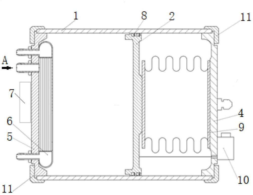
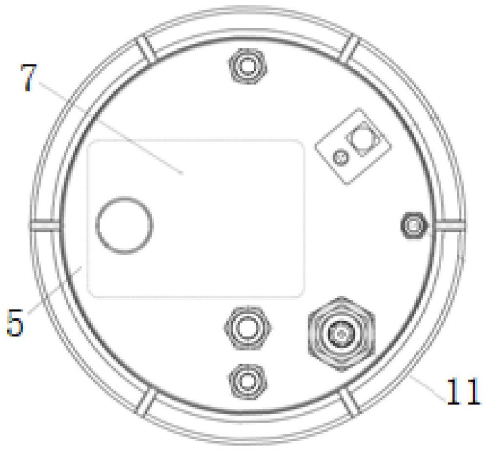
Integrated hydraulic oil tank
A hydraulic oil tank, integrated technology, applied in the direction of fuel supply tank device, fluid pressure actuating device, fluid pressure actuating system components, etc., can solve the problems of low functional integration and unfavorable aircraft weight reduction.
- Summary
- Abstract
- Description
- Claims
- Application Information
AI Technical Summary
Problems solved by technology
Method used
Image

Examples
Embodiment Construction
[0048] In order to make the technical solution of the present application and its advantages clearer, the technical solution of the present application will be further clearly and completely described in detail below in conjunction with the accompanying drawings. It can be understood that the specific embodiments described here are only part of the application Examples are only used to explain the present application, not to limit the present application. It should be noted that, for the convenience of description, only the parts related to the present application are shown in the drawings, and other relevant parts can refer to the general design. In the case of no conflict, the embodiments in the application and the technologies in the embodiments Features can be combined with each other to obtain new embodiments.
[0049] In addition, unless otherwise defined, the technical terms or scientific terms used in the description of the application shall have the usual meanings und...
PUM
 Abstract
Description
Claims
Application Information