
A detection device for wireless communication equipment

A technology of wireless communication equipment and detection devices, applied in the direction of mechanical equipment, springs/shock absorbers, machines/supports, etc., can solve the problems of affecting detection efficiency, inconvenient operation, and easily damaged components, etc., to achieve convenient use, Good adaptability, convenient and safe detection operation

Active Publication Date: 2021-12-17
南通赛意通信技术有限公司
View PDF0 Cites 0 Cited by
  • Summary
  • Abstract
  • Description
  • Claims
  • Application Information

AI Technical Summary

Problems solved by technology

[0004] Aiming at the deficiencies of the prior art, the present invention provides a detection device for wireless communication equipment, which solves the problem that the receiving pot needs to be disassembled and combined during detection due to the inconvenience of disassembling the larger receiving pot, which is extremely inconvenient to operate and seriously Affects the detection efficiency, and is easy to damage the components during the disassembly process

Method used


Image

  • A detection device for wireless communication equipment
  • A detection device for wireless communication equipment
  • A detection device for wireless communication equipment

Examples


Embodiment 1

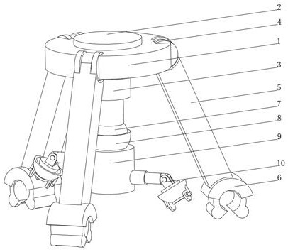
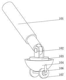
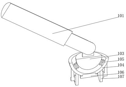
[0037] see Figure 1-3 , the present invention provides a technical solution: a detection device for wireless communication equipment, specifically comprising:

[0038] A fixed disk 1, the inner wall of the fixed disk 1 is fixedly connected with an electronic rotary table 2, and the electronic rotary table 2 runs through and is fixedly connected with a multi-stage telescopic rod 3;

[0039] The rotating seat 4 is arranged on one side of the fixed disk 1, the rotating seat 4 is embedded in the fixed disk 1 and fixedly connected with the fixed disk 1, the inner wall of the rotating seat 4 is connected with a rotating pole 5, and the rotating pole 5 is away from the rotating One end of the seat 4 is fixedly connected with a jaw 6;

[0040] Rotating ball 7, the top of the rotating ball 7 is fixedly connected with the bottom of the multi-stage telescopic rod 3, the outer part of the rotating ball 7 is provided with a rotating spherical shell 8, the bottom of the rotating spherical...

Embodiment 2

[0048] see Figure 1-5 On the basis of Embodiment 1, the present invention provides a technical solution: the jaw 6 includes an arc-shaped rotating disk 61, the inner wall of the arc-shaped rotating disk 61 is rotatably connected with a first claw 62, and the inner wall of the first claw 62 is rotatably connected with a The second claw 63, the top of the first claw 62 and the outer side of the second claw 63 are fixedly connected with a handle 64, the top of the arc-shaped rotating disc 61 is fixedly connected with the rotating pole 5, and the first claw 62 is connected with the second claw 63. The claws 63 are arranged oppositely, a clockwork spring is arranged between the first claw 62 and the second claw 63, and the bottom of the grip handle 64 is provided with a grip groove, and the grip on the first claw 62 and the second claw 63 The handle 64 is symmetrically arranged, and is provided with jaws 6. When clamping, the jaws 6 are placed above the receiving pot, and the jaws...


PUM


Abstract

The invention discloses a detection device for wireless communication equipment, which specifically includes: a fixed plate, the inner wall of the fixed plate is fixedly connected with an electronic rotating table, and the inside of the electronic rotating table is penetrated and fixedly connected with a multi-stage telescopic rod; a rotating seat, the The rotating seat is arranged on one side of the fixed plate, the rotating seat is embedded in the fixed plate and fixedly connected with the fixed plate, the inner wall of the rotating seat is rotatably connected with a rotating support rod, and the end of the rotating support rod away from the rotating seat is fixedly connected with a clip A claw; a rotating ball, the rotating ball is covered with a rotating spherical shell, and the bottom of the rotating spherical shell is fixedly connected with a fixed column. The present invention relates to the technical field of wireless communication equipment detection. The detection device of the wireless communication equipment avoids disassembly and assembly of the receiving pot, and the detection operation is convenient and safe. It can adapt to receiving pots of different sizes. It is safe and reliable to use.

Description

technical field [0001] The invention relates to the technical field of wireless communication equipment detection, in particular to a detection device for wireless communication equipment. Background technique [0002] With the rapid development of communication technology and the rapid construction of smart grid in recent years, it is often necessary to perform signal tests on a large number of different types of business units in the maintenance work of electric power communication to quickly judge whether the business signals are normal. There have been many wireless signal detection Mature methods include correlation detection, wavelet analysis, and sampling analysis in the time domain; spectrum analysis in the frequency domain, but currently collecting wireless signals mainly depends on receiving signals from the receiver. At present, due to the inconvenient disassembly of the large receiving pot, it is necessary to disassemble and assemble the receiving pot during dete...

Claims


Application Information

Patent Timeline
Patent Type & Authority Patents(China)
IPC IPC(8): F16M13/02F16M11/20F16M11/28F16M11/04F16M11/14F16F15/067
Inventor 刘建红
Owner 南通赛意通信技术有限公司
Learn More