
Disinfecting and killing module of cleaning robot

A cleaning robot and host technology, applied in the field of cleaning robots, can solve the problems of external environmental pollution, difficult dust and dirt cleaning, breeding of bacteria, etc., and achieve the effect of improving the disinfecting effect

Pending Publication Date: 2021-11-23
NANJING SUMEC INTELLIGENT TECH CO LTD
View PDF8 Cites 1 Cited by
  • Summary
  • Abstract
  • Description
  • Claims
  • Application Information

AI Technical Summary

Problems solved by technology

[0003] Because the cleaning robot has been in contact with the dirt on the ground for a long time, its internal air duct is prone to breed a large number of bacteria. Even a robot with the function of disassembling the dust box can hardly clean the dust and dust in the air duct inside the machine when the dust box is removed for dust cleaning. Clean up the dirt, and the bacteria that grow inside the machine cannot be treated
Based on the above reasons, after a long period of use, the cleaning robot will continue to breed bacteria inside. At the same time, since the cleaning robot will exhaust air to the external environment during operation, the bacteria growing inside the machine may follow the exhausted air into the external environment, further pollute the external environment

Method used


Image

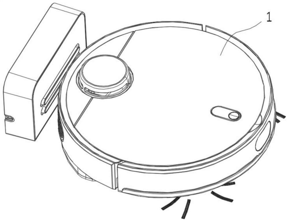
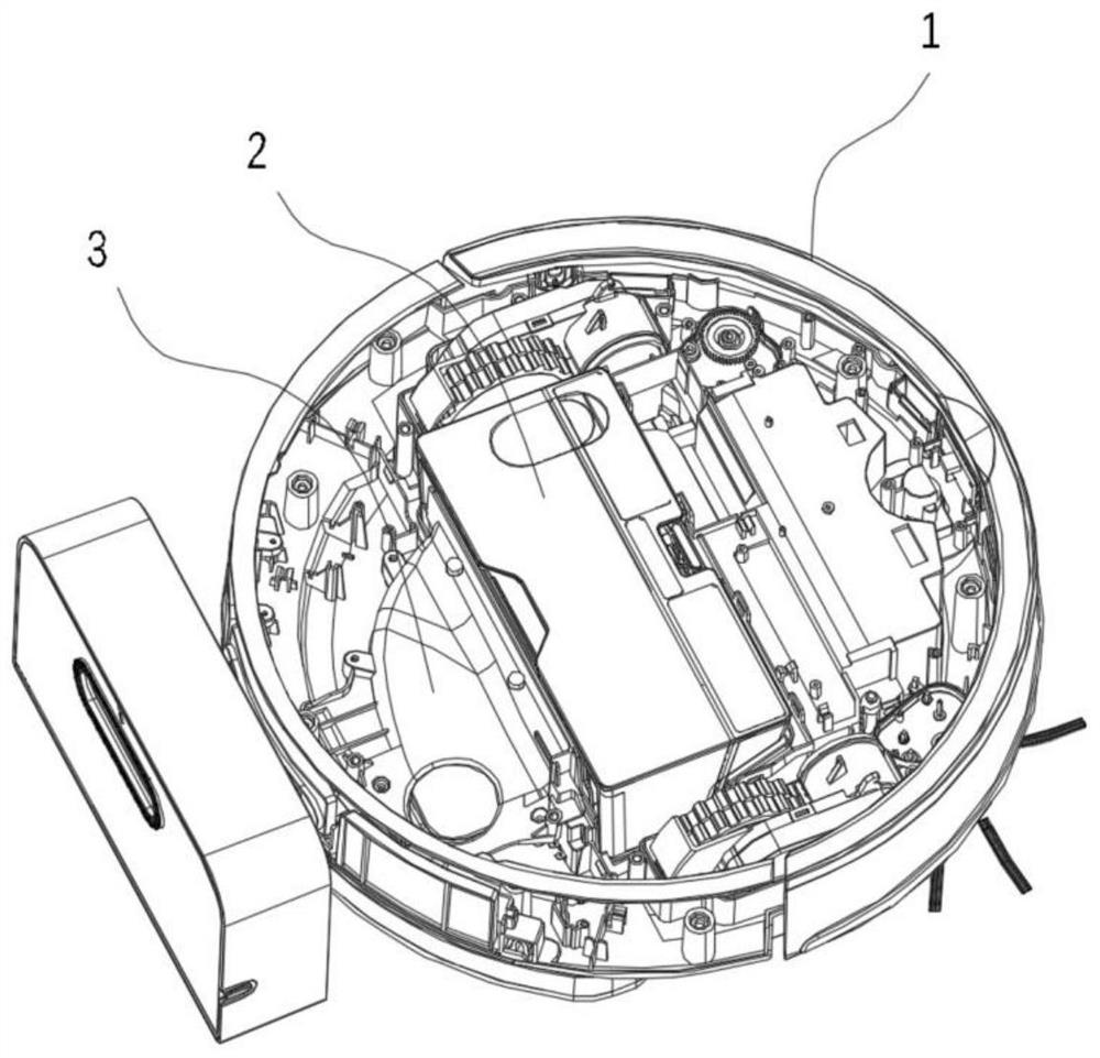
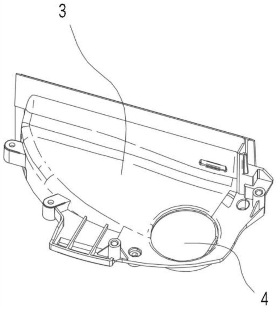
  • Disinfecting and killing module of cleaning robot
  • Disinfecting and killing module of cleaning robot
  • Disinfecting and killing module of cleaning robot

Examples


Embodiment 1

[0040] Such as Figure 6-7 As shown, the disinfecting element 7 is arranged on the air duct element 3. The disinfecting element 7 includes a main body element 13 and two groups of emitters protruding from the main body element 13. The main body element 13 includes electronic components such as necessary circuit boards and ion generating devices. Components also include sockets that connect to circuits in the host, etc. The two groups of emitters are positive emitter 10 a and negative emitter 11 a respectively, and the two groups of emitters are located in the air duct cavity 5 . disinfecting element 7 main parts are arranged on the outside of air duct assembly 3, and its main body element 13 is also provided with socket 8 and is connected with cleaning robot internal circuit (in the illustration of embodiment 2 and 3, socket 8 is not drawn, the actual This socket can be set as required).

[0041] Such as Figure 7 As shown, the two groups of emitters are separated by a separa...

Embodiment 2

[0043] In Embodiment 1, the disinfecting element 7 and the emitter are integrally structured, which results in the need to set a larger opening on the inner wall of the air duct cavity 5 of the air duct assembly, and at the same time, a partition with a larger area is provided in the air duct cavity 5 The plate affects the gas flow inside the air duct cavity. Therefore, this embodiment proposes a new arrangement of disinfecting components.

[0044] Such as Figure 8-9 As shown, the disinfecting element 7 includes a main body element 13, a positive emitter head 14 and a negative emitter head 15 which are separated from each other, and a mounting seat 12 is arranged on the outer wall of the air duct element 3, and the mounting seat 12 is a corresponding main body element 13 1. The cavity structure provided by the positive emitter 14 and the negative emitter 15, the main body element 13, the positive emitter 14 and the negative emitter 15 are all arranged in the mounting seat 12, a...

Embodiment 3

[0047] The main difference between this embodiment and embodiment 2 is that, on the basis of embodiment 2, the cleaning robot of this embodiment has the function of discharging the dirt accumulated in the dust box 2 to a unified recycling bin. like Figure 10-12 As shown, on the bottom plate of the main body 1 of the machine, a discharge channel 16 is provided. One end of the discharge channel 16 opens into the dust box 2, and the other end opens to the side wall of the main body. When in use, the cleaning robot moves to the recycling station, and the side The opening on the wall is docked with the opening of the recycle bin, the power unit in the recycle bin is started, and the dirt in the dust box 2 enters into the recycle bin through the discharge channel 16 . A cleaning robot with an emptying station is relatively well known in the art, and the relevant technical details of opening docking and switching are not described in detail here.

[0048] In this embodiment, the sp...


PUM


Abstract

The invention discloses a disinfecting and killing module of a cleaning robot. The cleaning robot comprises a host, a dust collecting box is arranged in the host, the disinfecting and killing module comprises an air duct element and a disinfecting and killing element, the air duct element comprises an air inlet and an air outlet, the air inlet is connected with an outlet of the dust collecting box, the air outlet is connected with a draught fan, an air duct cavity is formed between the air inlet and the air outlet, the opening in the lower portion of the air duct element is attached to a robot bottom plate, so that the air duct cavity forms a complete sealed cavity, and the disinfecting and killing element is integrated on the air duct cavity. In the working process of the cleaning robot, the disinfecting and killing element releases ions with a disinfecting and killing effect in an air duct of the cleaning robot, the effect of killing pollutants such as bacteria in the cleaning robot is achieved, meanwhile, when the cleaning robot works, air is sucked in from the external environment, purified and then exhausted into the external environment, and the effect of purifying external air is achieved.

Description

technical field [0001] The invention belongs to the technical field of cleaning robots, in particular to a cleaning robot disinfecting module. Background technique [0002] Cleaning robots are currently a very common household appliance. Cleaning robots are usually equipped with a roller brush and a suction port at the bottom. The dirt on the ground is sucked into the dust box in the robot through the suction port. Usually, the dust box is connected to an air duct assembly. , the air duct assembly is provided with a fan, which generates suction through the operation of the fan to realize the inhalation of dirt. [0003] Because the cleaning robot has been in contact with the dirt on the ground for a long time, its internal air duct is prone to breed a large number of bacteria. Even a robot with the function of disassembling the dust box can hardly clean the dust and dust in the air duct inside the machine when the dust box is removed for dust cleaning. The dirt is cleaned, ...

Claims


Application Information

Patent Timeline
Patent Type & Authority Applications(China)
IPC IPC(8): F24F8/30F24F13/02A47L11/24
CPCF24F8/30F24F13/02A47L11/24
Inventor 周峰周国扬刘楷
Owner NANJING SUMEC INTELLIGENT TECH CO LTD
Learn More