Sintering jig

A jig and ceramic sand technology, which is applied in the field of powder molding, can solve the problems of difficult positioning and support of the green body of the supporting jig, and achieve the effect of reducing the cost of the jig and improving the versatility

Pending Publication Date: 2021-11-23
SUZHOU ZHONGYAO TECH CO LTD
View PDF0 Cites 0 Cited by
  • Summary
  • Abstract
  • Description
  • Claims
  • Application Information

AI Technical Summary

Problems solved by technology

[0004] In other words, not all parts can have a supportable plane. When the bottom surface of the green body is a curved surface or a special-shaped surface, it is difficult for the planar support fixture to position and support the green body well.

Method used


Image

  • Sintering jig
  • Sintering jig
  • Sintering jig

Examples


Embodiment 1

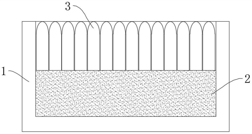
[0032] combine figure 1 with figure 2 As shown, the sintering fixture of this embodiment includes a ceramic container 1 , ceramic sand 2 filled in the ceramic container 1 , and a plurality of ceramic pillars 3 that can be vertically arranged in the ceramic container 1 and above the ceramic sand 2 . Wherein, the ceramic sand 2 has a filling height in the ceramic container 1, in other words, the ceramic sand 2 in the ceramic container 1 has a certain thickness, so that the ceramic column 3 can extend into the ceramic sand 2; the ceramic column 3 has a first Height, the ratio of the filling height of the ceramic sand 2 to the first height of the ceramic column 3 is between 0.5 and 1, so that the ceramic column 3 can extend into the ceramic sand 2 for a sufficient distance. A plurality of ceramic columns 3 are arranged in the ceramic container 1 in an array, and the distance between two adjacent ceramic columns 3 is between 0.1 and 0.2 mm, preferably, between the ceramic columns...

Embodiment 2

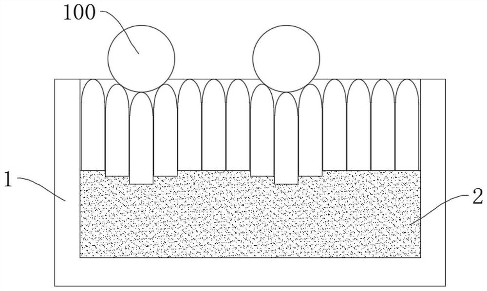
[0046] The structure and working principle of this embodiment are substantially the same as the sintering fixture of Embodiment 1, the difference is that, as Figure 5 As shown, the support body of this embodiment is a plurality of ceramic balls 4, and the plurality of ceramic balls 4 are divided into at least 3 layers and laid on the ceramic sand 2, so as to ensure that the green body 100 has a certain amount of penetration in the ceramic balls 4, and a single The diameter of the ceramic ball 4 is between 1.0mm and 10mm. The overall thickness (that is, the first height) of the multilayer ceramic ball 4 is substantially equal to the filling height of the ceramic sand 2 .


PUM

PropertyMeasurementUnit
Granularityaaaaaaaaaa
Diameteraaaaaaaaaa
Diameteraaaaaaaaaa

Abstract

The invention discloses a sintering jig. The sintering jig comprises a ceramic container, ceramic sand and a plurality of supporting bodies, the ceramic container is filled with the ceramic sand, the supporting bodies are movably arranged in the ceramic container and located above the ceramic sand, the ceramic sand has a filling height, each supporting body has a first height, the ratio of the filling height to the first height ranges from 0.5 to 1, the distance between every two adjacent supporting bodies ranges from 0.1 mm to 0.2 mm, and the particle size of the ceramic sand ranges from 10 micrometers to 1000 micrometers. According to the scheme of the sintering jig, the problems of positioning and supporting stability of a green body with the bottom face being the curved face or the special-shaped face can be well solved.

Description

technical field [0001] The invention relates to the technical field of powder molding, in particular to a sintering jig. Background technique [0002] Powder molding technology is a common part manufacturing technology. It obtains a green body through powder pressing, injection or gel forming, and then sinters and solidifies the green body at a high temperature to obtain a product. [0003] When sintering the green body, it is usually necessary to use a sintering fixture to carry and position the green body. In the traditional sintering process, the green body is usually supported by stacking plane stacks, but not all the bottom of the green body is flat, [0004] In other words, not all parts can have a supportable plane. When the bottom surface of the green body is a curved surface or a special-shaped surface, it is difficult for the planar support jig to position and support the green body well. Contents of the invention [0005] In order to overcome the defects in th...

Claims


Application Information

Patent Timeline
IPC IPC(8): F27D5/00
CPCF27D5/0012
Inventor 范振洋张善寿尹学荣
Owner SUZHOU ZHONGYAO TECH CO LTD
Why Eureka
Try Eureka