
In-situ shear apparatus

A shearing instrument, in-situ technology, used in instruments, scientific instruments, and testing the strength of materials by applying a stable shearing force. and other problems to achieve the effect of improving the detection speed and effect

Pending Publication Date: 2021-11-23
CHANGSHA UNIVERSITY OF SCIENCE AND TECHNOLOGY
View PDF0 Cites 0 Cited by
  • Summary
  • Abstract
  • Description
  • Claims
  • Application Information

AI Technical Summary

Problems solved by technology

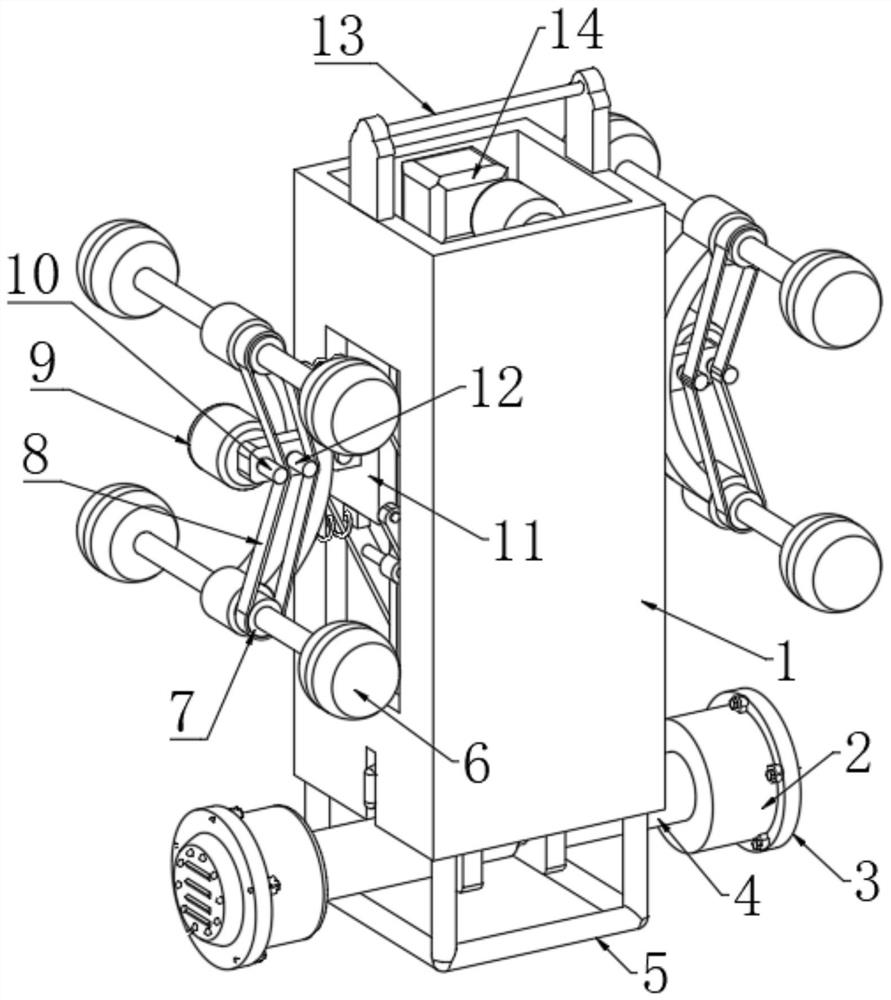
[0005] Aiming at the deficiencies of the prior art, the present invention provides an in-situ shearing instrument, which can effectively improve the detection speed and ease of use, and can detect the deep soil in situ without sampling, and can dive into the soil by itself It has the advantages of performing shear test in deep layers, and can also perform oblique shearing on the soil. It solves the problem that the existing instruments for detecting the shear strength of soil are inconvenient to detect the shear force of deeper soil layers. Deep soil often requires deep The soil can only be tested by digging, the sampling speed is slow, the cost is high, and the structure of the soil sample taken out is easily damaged, and it is difficult to maintain the original real strength of the obtained soil. Due to the limitation of the instrument, only the soil can be measured Problems with shear performance in the horizontal direction

Method used


Image

  • In-situ shear apparatus
  • In-situ shear apparatus
  • In-situ shear apparatus

Examples


Embodiment 1

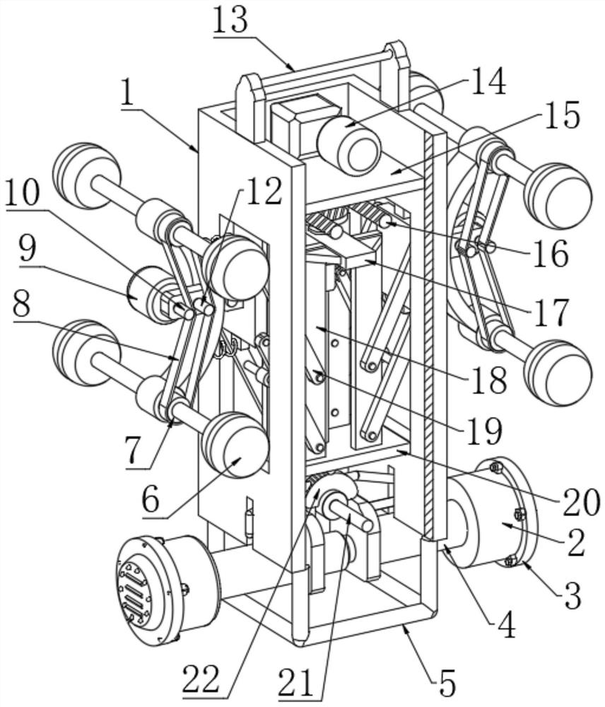
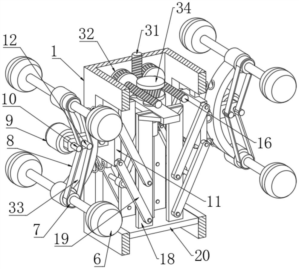
[0031] Refer to attached Figure 1-8, an in-situ shearing instrument, comprising a shell 1, a horizontal plate 15 and a mounting plate 20 are fixedly connected in the shell 1, through holes are opened on opposite sides of the shell 1, and there are connected in the two through holes Support plate 11, the side wall of support plate 11 is connected with walking mechanism, and walking mechanism comprises fixed plate 33, and the two ends of fixed plate 33 are all connected with rotating shaft through the second rolling bearing rotation, and the two ends of two rotating shafts are all fixedly connected with traveling wheel 6. One side of the fixed plate 33 is rotationally connected with the side wall of the support plate 11 through a pin, and the other side of the fixed plate 33 is fixedly connected with a fixed rod, and the motor 9 is fixedly connected to the rod wall of the fixed rod, and the output end of the motor 9 Through the side wall of the fixed rod and fixedly connected w...

Embodiment 2

[0033] Embodiment 2: the difference based on Embodiment 1 is;

[0034] Refer to attached Figure 2-4 , the transmission mechanism includes a screw rod 38, the two ends of the screw rod 38 are respectively connected in rotation with the opposite side of the horizontal plate 15 and the mounting plate 20 through the second ball bearing, and the rod wall of the screw rod 38 is connected in rotation through the third rolling bearing. Positioning plate 17, the two ends of positioning plate 17 are all fixedly connected with the inner side of housing 1, and the relative both sides of positioning plate 17 are all symmetrically fixedly connected with two support rods 18, and the lower ends of two support rods 18 are all connected with mounting plate 20 The upper end of the support plate 11 is fixedly connected, and the two opposite sides of the support plate 11 are rotatably connected with two swing arms 19 through pins, and the ends of the two swing arms 19 away from the support plate ...

Embodiment 3

[0036] Embodiment 3: the difference based on embodiment 1 is;

[0037] Refer to attached Figure 5-7 The shear mechanism includes two backing plates 30, a hydraulic cylinder 29 is fixedly connected between the two backing plates 30, a half gear 22 is fixedly connected to the shaft wall of the rotating shaft, and a reversing motor is fixedly connected to the side wall of the mounting plate 20 26. The output end of the reversing motor 26 is fixedly connected with the gear 27, the gear 27 meshes with the half gear 22, the end of the backing plate 30 away from the hydraulic cylinder 29 is fixedly connected with the first threaded column, and the backing plate 30 is threaded through the first threaded post There is a transmission connecting rod 4, and the length of the driving connecting rod 4 can be replaced with spare parts of different lengths according to actual usage requirements. There is a shearing head 2, and the side wall of the backing plate 30 is slidably sleeved with a...


PUM


Abstract

The invention relates to the technical field of soil body detection, and discloses an in-situ shear apparatus. The shear apparatus comprises a shell; a transverse plate and a mounting plate are fixedly connected in the shell; through holes are formed in the two opposite sides of the shell; supporting plates are connected in the two through holes; walking mechanisms are connected to the side walls of the supporting plates; a transmission mechanism is jointly connected between the transverse plate and the mounting plate, and the transmission mechanism is connected with the supporting plates; a transmission shaft is rotationally connected into the shell through a first rolling bearing; a shearing mechanism is connected to the shaft wall of the transmission shaft; a handle is fixedly connected to the upper end of the shell; and a supporting frame is fixedly connected to the lower end of the shell. According to the in-situ shear apparatus, the detection speed and the use convenience can be effectively improved, a deep soil body can be detected in situ without sampling, and the in-situ shear apparatus can automatically dive into the deep layer of the soil body for a shear test and obliquely shear the soil body.

Description

technical field [0001] The invention relates to the technical field of soil detection, in particular to an in-situ shearing instrument. Background technique [0002] Soil is composed of solid particles, and the connection strength between soil particles is much smaller than the strength of the soil particles themselves. Therefore, under the action of external force, the soil particles are displaced from each other, causing one part of the soil to slide relative to the other part, and the soil resists This sliding performance is called the shear resistance of the soil. The displacement resistance of the soil is often characterized by the shear strength of the soil. At present, the method of testing the soil is to place the soil sample in a shear box composed of an upper box and a lower box. In this method, a vertical load is applied on it, so that the soil sample experiences a normal force on the cross section, the lower box is fixed, and a horizontal force is applied to the ...

Claims


Application Information

Patent Timeline
Patent Type & Authority Applications(China)
IPC IPC(8): G01N3/02G01N3/24
CPCG01N3/02G01N3/24
Inventor 方薇石立君
Owner CHANGSHA UNIVERSITY OF SCIENCE AND TECHNOLOGY
Learn More