Multi-row thrust ball bearing

A ball bearing and thrust technology, applied in the directions of bearings, ball bearings, shafts and bearings, can solve the problem of non-existence and achieve the effect of increasing the load capacity

Pending Publication Date: 2021-11-23
NSK LTD
View PDF18 Cites 2 Cited by
  • Summary
  • Abstract
  • Description
  • Claims
  • Application Information

AI Technical Summary

Problems solved by technology

[0009] In addition, in the thrust ball bearing described in the above-mentioned Patent Document 1, in order to prevent the rolling elements (balls) from falling out of the pockets of the cage, claw-shaped protrusions are provided on the periphery of the opening of the pockets. figure 1 As shown in (b) etc., since the claw-shaped protrusions are protrudingly provided on the flat surface of the cage in the circumferential and radial directions of the cage, in order to prevent the claw-shaped protrusions from interfering with the pair of raceway rings, the thin-walled thrust ball bearing There is a limit
[0010] In addition, in the thrust ball bearing described in Patent Document 2, since the above-mentioned claw-like protrusions are not provided in the cage, interference between the claw-like protrusions and the pair of raceway rings is not a problem. There is a claw-like protrusion where the rolling elements fall out of the pockets. Therefore, it is necessary to ensure that the wall thickness of the cage is such that the rolling elements do not fall out of the pockets. Therefore, in this case, there is a limit to the thinning of the thrust ball bearing.

Method used


Image

  • Multi-row thrust ball bearing
  • Multi-row thrust ball bearing
  • Multi-row thrust ball bearing

Examples


Embodiment Construction

[0080] Hereinafter, one embodiment of the multi-row thrust ball bearing according to the present invention will be described in detail based on the drawings.

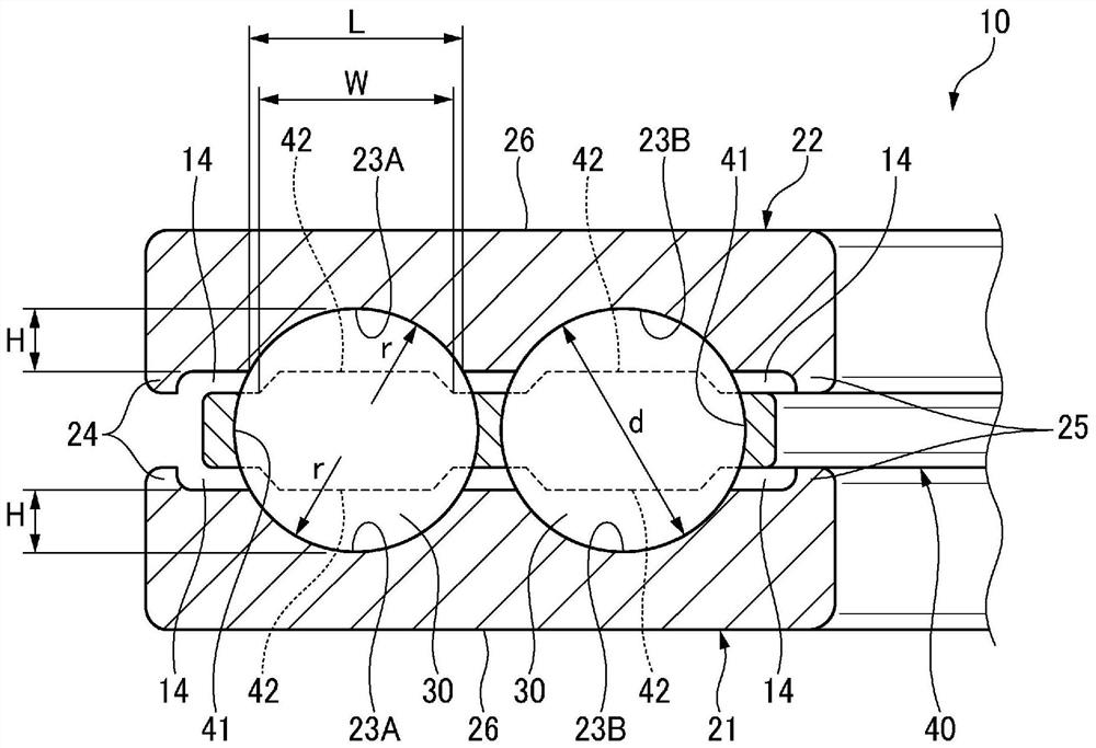
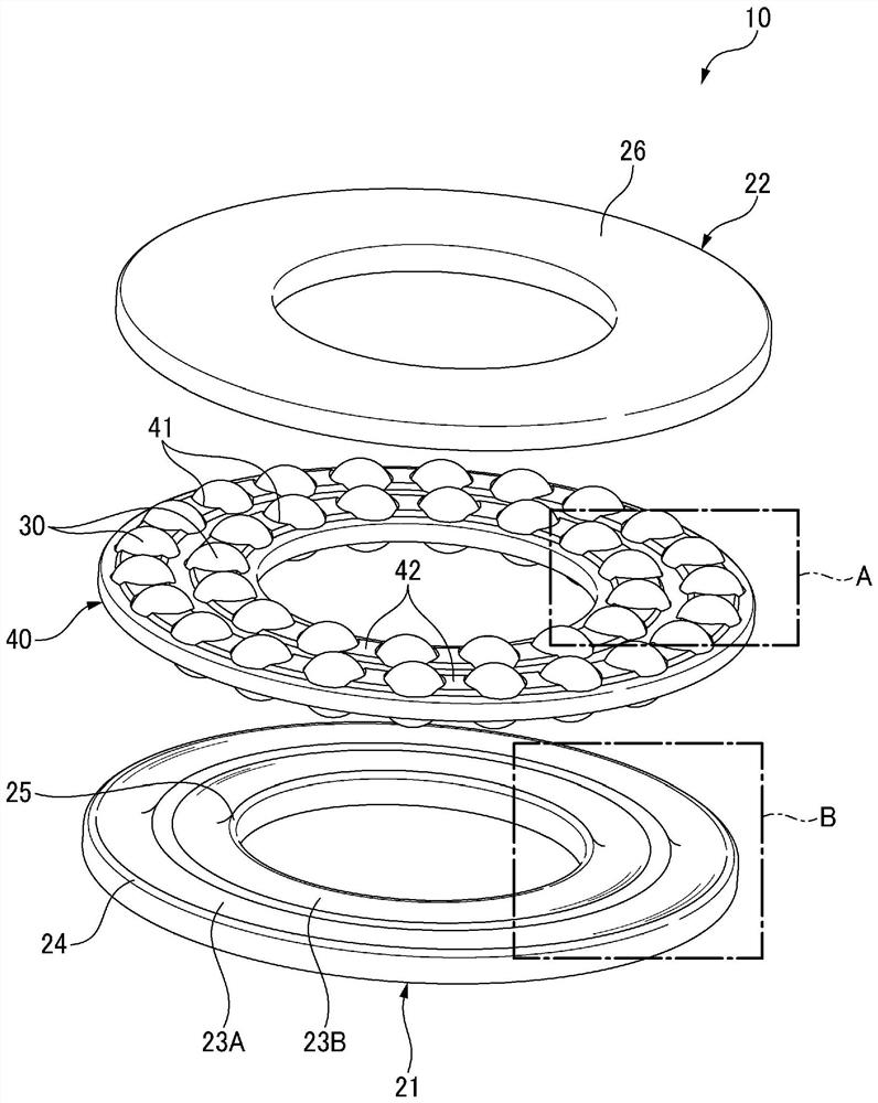
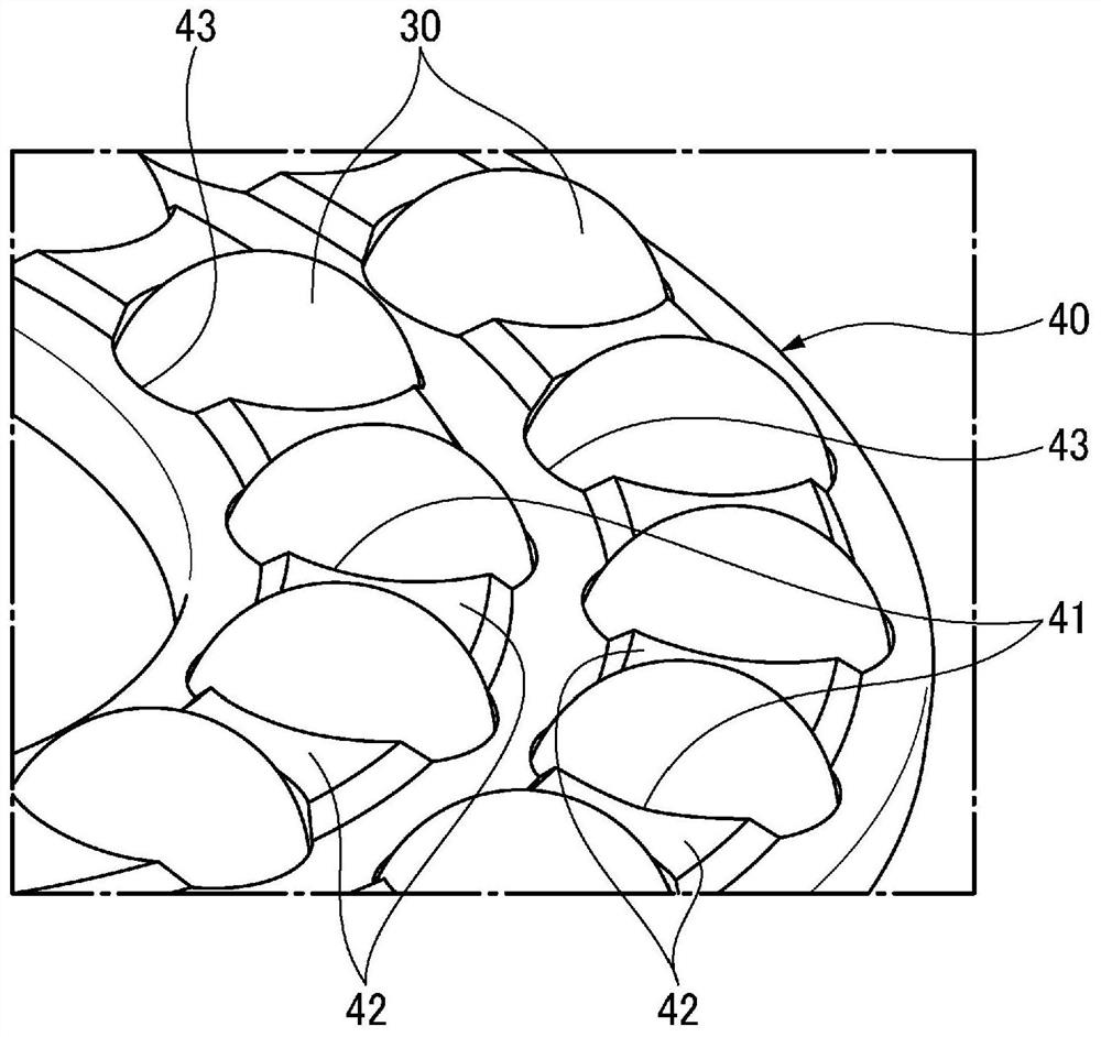
[0081] Such as figure 1 as well as figure 2 As shown, the multi-row thrust ball bearing 10 of this embodiment includes: a pair of raceway rings 21, 22 formed in an annular shape and arranged in parallel axially apart from each other; a plurality of balls (rolling elements) 30, which is rotatably arranged between the pair of raceway rings 21, 22; and a cage 40 which has a plurality of pockets 41 capable of rolling the plurality of balls 30 and holding the plurality of balls 30 in Keep at specified intervals.

[0082] Here, refer to Figure 4 A pair of raceway rings 21 and 22 are formed in an annular shape, and are provided with a plurality of rows of raceway grooves 23 on surfaces facing each other. In addition, the multi-row rolling groove 23 refers to the rolling groove 23 in two rows, and specifically includes th...


PUM


Abstract

Provided is a multi-row thrust ball bearing that has a large load capacity, is thin, and can bear a radial load. According to the present invention, facing surfaces of a pair of races (21, 22) have multiple rows of race grooves (23A, 23B) that are provided along the radial direction. Circumferential edges of openings of pockets (41) of a cage (40) protrude to form tab-shaped protrusions (42) that are oppositely arranged in only the circumferential direction of the cage. The maximum radial-direction width W of the tab-shaped protrusions (42) is smaller than the maximum radial-direction width L of the race grooves (23).

Description

technical field [0001] The present invention relates to a multi-row thrust ball bearing including a plurality of balls arranged in multiple rows in the radial direction. Background technique [0002] Conventionally, thrust needle roller bearings have been used in order to accommodate large thrust loads in automotive bearings. In the thrust needle roller bearing, the raceway ring is formed of a washer-shaped thin plate, so that the overall thickness can be reduced, and since the needle roller and the raceway ring are in line contact, the contact area is large and the load capacity is large. [0003] On the other hand, since the balls of the thrust ball bearing are in point contact with the ball grooves, the load capacity is smaller than that of the thrust needle bearing. However, since the contact area is small, there is an advantage that friction is small and radial loads are supported to some extent. [0004] As a thrust ball bearing, for example, Patent Document 1 disclo...

Claims


Application Information

Patent Timeline
Patent Type & Authority Applications(China)
IPC IPC(8): F16C19/10
CPCF16C19/10F16C33/3856F16C33/3887F16C33/40F16C33/585F16C33/6614F16C33/6651F16C2240/40F16C2326/01F16C33/3843F16C33/583
Inventor 迫田裕成菊池文千原佑太
Owner NSK LTD
Why Eureka
Try Eureka