Moving contact push mechanism of magnetic latching relay

A magnetic latching relay and push mechanism technology, applied in electromagnetic relays, electromagnetic relay details, relays, etc., can solve the problems of large matching gap between the push point and the push block, the inability to increase the contact opening distance, and aggravate the wear and tear of the mechanism, etc. Achieve the effects of increasing safety and reliability, large gap, and increasing contact pressure

Active Publication Date: 2016-01-13
SOOAR TIANJIN ELECTRICAL EQUIP CO LTD
View PDF10 Cites 4 Cited by
  • Summary
  • Abstract
  • Description
  • Claims
  • Application Information

AI Technical Summary

Problems solved by technology

Since the moving reed is fixedly connected to the lead-out end of the moving spring, the connection and breaking of the moving contact is realized by the elastic deformation of the moving reed itself, which is limited by the deformation of the moving reed itself, so that the moving contact and the static contact of the contact system The separation distance is small, and the contact distance cannot be increased
The movement of the push block in the horizontal guide groove makes the push friction force large and aggravates the wear of the mechanism; the matching gap between the push point of the armature part and the push block is large, making the fit not compact, and the rotation and sliding will also increase the friction

Method used


Image

  • Moving contact push mechanism of magnetic latching relay
  • Moving contact push mechanism of magnetic latching relay
  • Moving contact push mechanism of magnetic latching relay

Examples


Embodiment Construction

[0034] In order to make the object, technical solution and advantages of the present invention clearer, the present invention will be further described in detail below in conjunction with the accompanying drawings and specific embodiments.

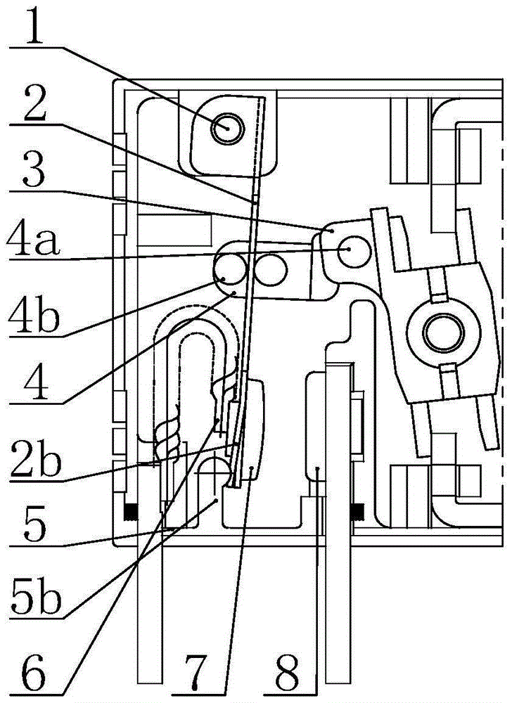
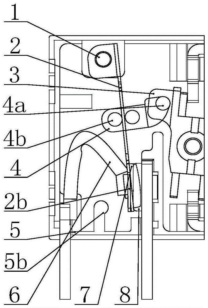
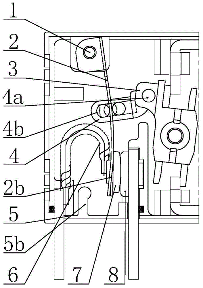
[0035] The magnetic latching relay moving contact pushing mechanism provided by the present invention includes:

[0036] The moving contact is the fixed connection between the second end of the moving reed and the moving contact, and the flexible wire connection between the tail of the moving contact and the moving pin. The flexible wire is n-shaped, and the n-shaped flexible wire connection is mainly to make the 1. The direction of the current flowing through the static contacts is the same, and other shapes such as U-shaped or M-shaped, as long as the current direction of the dynamic and static contacts is the same, this is the connection method;

[0037] There are three cylinders on the top of the push block, two adjacent cylinders clam...


PUM


Abstract

The invention provides a moving contact push mechanism of a magnetic latching relay. The moving contact push mechanism comprises a contact system, an armature part and a push block, wherein the contact system comprises a moving contact and a static contact, the armature part drives the push block to move, and the push block moves to drive the moving contact to swing so as to achieve connection and disconnection of the moving contact and the static contact; a movable contact spring of the moving contact is an elastic component and is shaped as a rectangular sheet, a first end part of the moving contact is of a rotation structure, and a second end part of the moving contact is of a swinging structure; the push block is movably connected to the middle part of the movable contact spring, a structure having a guidance effect is arranged between the push block and a relay shell, and the push block and the armature part are directly or indirectly connected; and the moving contact and a movable leading-out pin are connected by a flexible connection wire. By the moving contact push mechanism, a transmission structure and a current direction are changed, the transmission loss is reduced, the contact opening distance is increased, and the high-current bearing ability is improved.

Description

technical field [0001] The invention relates to a pushing mechanism of a relay, in particular to a moving contact pushing mechanism of a magnetic latching relay. Background technique [0002] In the existing magnetic latching relay contact system, the moving reed of the moving contact is composed of two or three copper alloy metal sheets. Each copper alloy metal sheet must not only have good elastic deformation recovery, but also have good electrical conductivity. Sex, resulting in increased material costs; the use of multi-piece moving reed structure is to provide different directions of reaction force for the push block when the contact is closed and disconnected, so that the push block is subjected to pressure when the contact is closed and disconnected. The force of the moving reed is equal, and the processing technology requirements are high. The three-piece structure makes the process of the moving contact contacting the static contact constant, and there is no relati...

Claims


Application Information

Patent Timeline
Patent Type & Authority Applications(China)
IPC IPC(8): H01H50/58
CPCH01H50/58
Inventor 南寅陈伟刚于纪磊刘志明
Owner SOOAR TIANJIN ELECTRICAL EQUIP CO LTD
Why Eureka
Try Eureka