Bathing device

A shower gel and shower technology, applied in the field of bathing devices, can solve the problems of insufficient convenience in the use of bathing devices, and achieve the effects of improving convenience and service life, improving convenience, and convenient use

Active Publication Date: 2021-11-26
ZHEJIANG HUALE TECH CO LTD
View PDF13 Cites 3 Cited by
  • Summary
  • Abstract
  • Description
  • Claims
  • Application Information

AI Technical Summary

Problems solved by technology

[0006] The purpose of the present invention is to address the above-mentioned problems existing in the prior art, and propose a bathing device, which solves the technical problem of insufficient convenience of use of the existing bathing device

Method used


Image

  • Bathing device
  • Bathing device
  • Bathing device

Examples


Embodiment 1

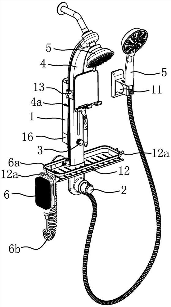
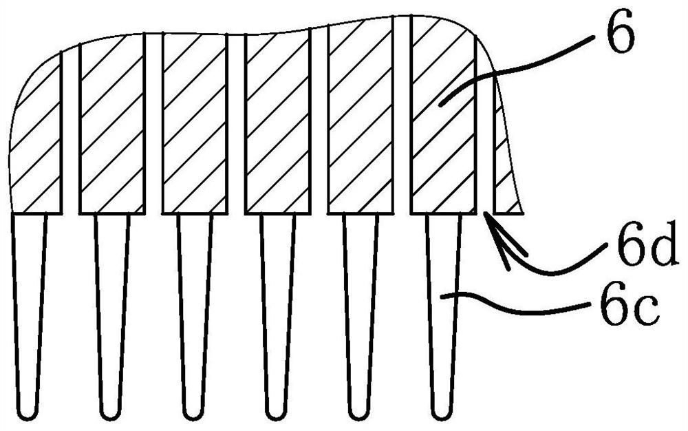
[0050] Such as Figure 1-Figure 4 As shown, a bathing device includes a liquid storage tank 1, a multi-water channel switching valve 2, a mixing body 3, a shower rack 4, a foam spraying piece 6 and two clean water spraying pieces 5, and one clean water spraying piece 5 is The top spray shower, another clear water spraying part 5 is a hand shower. The foam ejection member 6 is provided with a spout 6d, and the foam ejection member 6 is also provided with a scrubbing body for scrubbing. The spout 6d and the scrubbing body are located on the same surface of the foam ejection member 6. The foam ejection part 6 is a brush, and the rubbing body on the foam ejection part 6 front is a bristle 6c, and the spout 6d and the bristle 6c are all arranged on the front of the foam ejection part 6, and the spout 6d is positioned at the gap between the bristles 6c. In order to hold the foam ejection piece 6 conveniently, the foam ejection piece 6 is provided with a grip block or handle, or the...

Embodiment 2

[0062] The multi-water circuit switching valve 2 in the bathing device is provided with a second water outlet 2c, the clean water spouting part 5 is one of the hand shower or the overhead shower, and the structure and pipeline of the shower rack 4 are adjusted adaptively. Other structures are the same as in Embodiment 1.

Embodiment 3

[0064] Such as Figure 10 Shown, compared to embodiment one [such as Figure 6 and Figure 7 As shown], the valve body 3b and the valve core 3a are integrally formed to form the main body 31 of the mixture 3, and the water inlet channel 3b4, the water negative pressure channel 3a3 and the liquid outlet channel 3b5 are integrally arranged in the main body 31 to form the water passage 313, and the The air passage 3b6 is integrally arranged in the main body 31 with the air inlet hole 3a2 to form an air inlet passage 312 , and the liquid inlet passage 3b7 is integrally arranged in the main body 31 with the liquid inlet hole 3a1 to form a liquid inlet passage 311 . That is to say, the water passage 313 includes a water inlet passage 3b4, a water negative pressure passage 3a3 and a liquid outlet passage 3b5 sequentially arranged in the main body 31, and the air intake passage 312 includes an air inlet passage 3b6 and an The air inlet 3a2 and the liquid inlet passage 311 include a ...


PUM


Abstract

The invention provides a bathing device, and belongs to the technical field of bathing devices. The bathing device solves the problem that an existing bathing device is insufficient in use convenience and the like. The bathing device comprises a liquid storage barrel used for storing shower gel, a multi-waterway switching valve used for switching waterways and a clear water spraying part used for spraying clear water, the multi-waterway switching valve comprises a first water outlet part and at least one second water outlet part, the second water outlet parts are connected with the clear water spraying part, the bathing device further comprises a foam spraying part and a mixture used for mixing shower gel and clear water, the mixture is communicated with the liquid storage barrel, negative pressure can be generated on a communication channel between the liquid storage barrel and the mixture when water passes through the mixture, the first water outlet part is connected with the water inlet part of the mixture, and the foam spraying part is only connected with the liquid outlet part of the mixture. According to the bathing device, the use convenience is improved.

Description

technical field [0001] The invention belongs to the technical field of bathing devices, and relates to a bathing device. Background technique [0002] Showering is one of the commonly used ways to clean the body, and now people generally use a shower head when showering. During the shower, first turn on the shower to wet the body, then turn off the shower, apply the shower gel on the body and scrub, and finally turn on the shower to rinse off the shower gel. This bathing method needs to be carried out in three stages. During the process of applying the shower gel, the shower is turned off, resulting in a drop in temperature. Especially in winter, the bathing experience is not good. [0003] In order to improve the comfort and convenience of bathing, Chinese patent documents publicly proposed a shower with bathing liquid [Application No.: CN201511002107.0; Publication No.: CN 105395115 A], including a liquid inlet, a bath bottle, diverter valve. The liquid inlet is install...

Claims


Application Information

Patent Timeline
Patent Type & Authority Applications(China)
IPC IPC(8): A47K3/28E03C1/04E03C1/046E03C1/06
CPCA47K3/281E03C1/04E03C1/0408E03C1/0409E03C1/046E03C1/06Y02A20/40
Inventor 林泓鑫
Owner ZHEJIANG HUALE TECH CO LTD
Why Eureka
Try Eureka