
Cast iron mold with gap interlayer

A cast iron mold and interlayer technology, which is applied in the field of cast iron molds, can solve the problems affecting the comprehensive production capacity of the cast iron machine, the life of the cast iron mold is not up to expectations, and the high equipment operating cost, so as to save labor hours, reduce equipment operating costs, and achieve comprehensive production capacity. improved effect

Pending Publication Date: 2021-11-26
SHILIN LUOHE METALLURGY EQUIP
View PDF0 Cites 0 Cited by
  • Summary
  • Abstract
  • Description
  • Claims
  • Application Information

AI Technical Summary

Problems solved by technology

It can be seen that under the working conditions, the cast iron mold is under the alternating heat load for a long time, the working condition is very bad, thermal fatigue cracks or fractures are prone to occur, and frequent shutdowns and replacements occur, which affects the comprehensive production capacity of the cast iron machine
The same industry in China has also optimized the structural design of cast iron molds to varying degrees. The selection of materials has been continuously explored and tried, experimented with gray cast iron, nodular cast iron, heat-resistant cast iron, low-carbon cast steel, etc. Composite refractory material in the inner cavity and heat-resistant steel in the working layer. These improvements have achieved certain results, but they are not very ideal. The main performance is that the life of the cast iron mold is not up to expectations and the operating cost of the equipment is high.

Method used


Image

  • Cast iron mold with gap interlayer
  • Cast iron mold with gap interlayer
  • Cast iron mold with gap interlayer

Examples


Embodiment Construction

[0023] The present invention will be described in further detail below in conjunction with the accompanying drawings and specific embodiments.

[0024] In order to make the purpose, technical solutions and advantages of the present invention clearer, the technical solutions in the present invention will be clearly and completely described below in conjunction with the accompanying drawings. Apparently, the described implementations are part of the implementations of the present invention, not all of them. implementation. Based on the implementation manners in the present invention, all other implementation manners obtained by persons of ordinary skill in the art without creative efforts fall within the protection scope of the present invention.

[0025] Therefore, the following detailed description of the embodiments of the present invention provided in the accompanying drawings is not intended to limit the scope of the claimed invention, but merely represents selected embodim...


PUM


Abstract

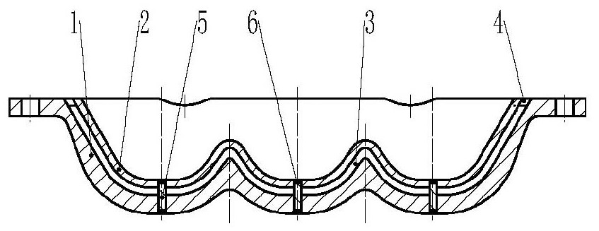
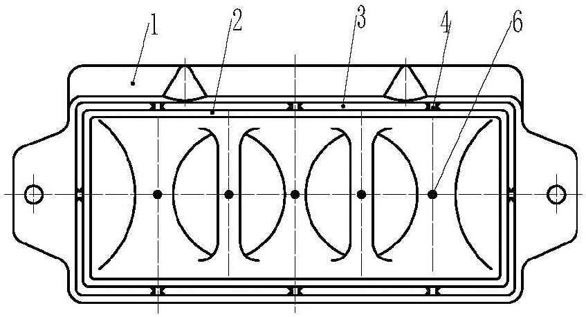
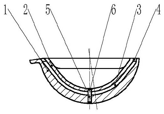
A cast iron mold with a gap interlayer comprises a bottom layer, a working layer and a gap layer arranged between the bottom layer and the working layer, the bottom layer and the bottom of the working layer are welded and connected through cotter pins, supporting blocks are located on the peripheral edge of the cast iron mold and are adopted for welding and supporting, cotter pin welding is that the cotter pins penetrate through the bottom layer and the working layer, and the two ends of the cotter pins are welded through plug welding seams. The thickness of the working layer is 1 / 2 of that of the bottom layer. The gap layer is arranged between the working layer and the bottom layer, a large amount of cooling water sprayed on an iron block can enter the gap layer between the working layer and the bottom layer during cast iron production, meanwhile, the working layer and the bottom layer are cooled, the thermal load of the working layer and the bottom layer is reduced, therefore the thermal fatigue life of the cast iron mold is prolonged, and the replacement frequency of the cast iron mold is reduced.

Description

technical field [0001] The invention relates to a vulnerable part of auxiliary equipment for blast furnace ironmaking, in particular to a cast iron mold with a gap interlayer for a cast iron machine. Background technique [0002] Iron casting machine is an indispensable auxiliary equipment for iron and steel enterprises. Its function is to continuously cast molten iron produced by blast furnace or non-blast furnace ironmaking process into iron blocks. The molten iron produced is continuously cast into iron blocks to ensure the continuous and normal production of the ironmaking blast furnace, and at the same time, it can effectively solve the safety problems in the transportation of the blast furnace molten iron to different places and the large power consumption problem caused by the cooling of the molten iron. It is a necessary molten iron continuous casting equipment for domestic and foreign iron and steel enterprises. [0003] The cast iron mold accounts for about 35% of...

Claims


Application Information

Patent Timeline
Patent Type & Authority Applications(China)
IPC IPC(8): B22D3/00
CPCB22D3/00
Inventor 张进阮键田周田京卫易先合李哲伦安吉林帅锋
Owner SHILIN LUOHE METALLURGY EQUIP
Learn More