Supercharge Your Innovation With Domain-Expert AI Agents!

Injection-molded product demolding mechanism of injection molding machine

A technology of injection molding products and demoulding mechanism, applied in the field of product processing, can solve problems such as easy slipping of products, and achieve the effect of not easy to fall and stable clamping process

Pending Publication Date: 2021-11-26
厦门诚畅欣工贸有限公司
View PDF0 Cites 1 Cited by
  • Summary
  • Abstract
  • Description
  • Claims
  • Application Information

AI Technical Summary

Problems solved by technology

[0003] After the product is formed, the product needs to be taken out from the mold cavity. However, the existing way of taking the mold is to clamp it out directly with tools such as clips, and some products are easy to slip off. Therefore, a demoulding mechanism is urgently needed to solve the problem. the problem

Method used


Image

  • Injection-molded product demolding mechanism of injection molding machine
  • Injection-molded product demolding mechanism of injection molding machine
  • Injection-molded product demolding mechanism of injection molding machine

Examples


Embodiment 1

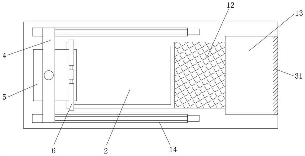
[0028] After the molding is completed, start the second linear motor to drive the connecting rod to move up, thereby driving the ejector rod 23 to lift the product upwards. After the jacking, the first linear motor is started to drive the fixed frame 4 along the figure 2 The guide groove 14 in the middle slides to the right. At the same time, during the movement, start the first lifting motor to make the adjustment plate 5 move down. When the vertical part of 5 is in contact with the product, start the first lifting motor again, so that the adjustment plate 5 continues to move down to contact with it, and then the electric suction cup is activated to suck the product, and then the first lifting motor drives the adjustment plate 5 And the product moves upwards synchronously. During the upward movement, the second lifting motor starts to drive the lifting seat 7 to move upwards, so that the connecting handle 71 drives the sliding bolt to slide in the adjusting hole 62, so that t...

Embodiment 2

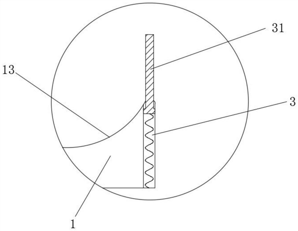
[0029] Embodiment 2: In this embodiment, on the basis of Embodiment 1, the spring board 31 and the receiving trough 13 can be directly integrated, and the height of the spring board 31 can be set as required.

Embodiment 3

[0030] Embodiment 3: In this embodiment, on the basis of Embodiment 1, the bottom plate 21 can be directly set to be movable, but it is seamlessly connected with the inner wall of the bottom mold 2, and under the bottom plate 21 An electric cylinder is provided, so that the lifting of the product can be realized directly by raising the bottom plate 21 .


PUM


Abstract

The invention relates to the technical field of product processing, in particular to an injection-molded product demolding mechanism of an injection molding machine. The injection-molded product demolding mechanism comprises a workbench, a bottom mold, a fixing frame and an adjusting plate. A controller is embedded in the side wall of the workbench, the bottom mold is embedded in the workbench, a sliding plate and a receiving groove are further arranged on one side of the bottom mold, and an elastic plate is further arranged at the edge of the receiving groove. A bottom plate connected with the bottom mold into a whole is arranged in the bottom mold, and multiple sets of ejector rods which are each of a cylindrical structure are movably arranged below the bottom plate. The fixing frame is slidably arranged on the workbench through a first linear motor and located on other side of the bottom mold, the adjusting plate which is of an L-shaped structure is movably installed on the fixing frame through a first lifting motor, and a plurality of electric suction cups are externally embedded in the side walls of the two sides of the adjusting plate. The injection-molded product demolding mechanism can effectively clamp molded products and products in an irregular shape, the clamping process is more stable, and the products are not likely to fall off.

Description

technical field [0001] The invention relates to the technical field of product processing, in particular to a demoulding mechanism for injection molded products of an injection molding machine. Background technique [0002] Injection molding machine is the main molding equipment for making thermoplastics or thermosetting plastics into various shapes of plastic products using plastic molding molds. The injection molding machine heats the plastic, applies high pressure to the molten plastic, and makes it shoot out to fill the mold cavity. The working principle of the injection molding machine is to use the thrust of the screw (or plunger) to inject the plasticized molten plastic into the closed mold cavity, and obtain the product after curing and shaping. [0003] After the product is formed, the product needs to be taken out from the mold cavity. However, the existing way of taking the mold is to clamp it out directly with tools such as clips, and some products are easy to s...

Claims


Application Information

Patent Timeline
IPC IPC(8): B29C45/40B29C45/42B29C45/17
CPCB29C45/401B29C45/4225B29C45/1769
Inventor 刘文强马有进
Owner 厦门诚畅欣工贸有限公司
Features
  • R&D
  • Intellectual Property
  • Life Sciences
  • Materials
  • Tech Scout
  • Unparalleled Data Quality
  • Higher Quality Content
  • 60% Fewer Hallucinations
Learn More