Manipulator capable of clamping plastic parts

A technology for manipulators and plastic parts, applied in the field of manipulators, can solve problems such as easy burns to the body, insufficient structural strength, long labor hours, etc., and achieve the effects of overcoming personnel burn safety accidents, reducing personnel labor intensity, and improving product qualification rates.

Pending Publication Date: 2021-11-26
DONGFENG VISTEON AUTOMOTIVE TRIM SYST CO LTD
View PDF4 Cites 0 Cited by
  • Summary
  • Abstract
  • Description
  • Claims
  • Application Information

AI Technical Summary

Problems solved by technology

[0004] 1. When the injection molding process is completed and the mold is opened, the injection molded parts are not completely cooled down and the temperature is high. The operator walks into the equipment and picks up the parts manually, which is easy to burn and the body and head are easily scratched and scratched by the mold steel. There are a series of safety hazards. question;
[0005] 2. The operator walks into the equipment, then manually picks up the parts, and then walks out and presses the start button. The travel distance is long, and the labor time is long. During this period, the equipment cannot operate, there are equipment waiting for people, and the equipment load is insufficient;
[0006] 3. The plastic parts are not completely cooled and solidified when they are demoulded, the structural strength is insufficient, and there are problems of scratches / deformation on the surface of the parts during manual grasping;
[0007] 4. The labor intensity of the operator to pick up the parts is high, and the cycle operation cannot meet the output of one day's shift

Method used


Image

  • Manipulator capable of clamping plastic parts
  • Manipulator capable of clamping plastic parts
  • Manipulator capable of clamping plastic parts

Examples


Embodiment Construction

[0026] The present invention will be further described in detail below in conjunction with the accompanying drawings and specific embodiments to facilitate a clear understanding of the present invention, but they do not limit the present invention.

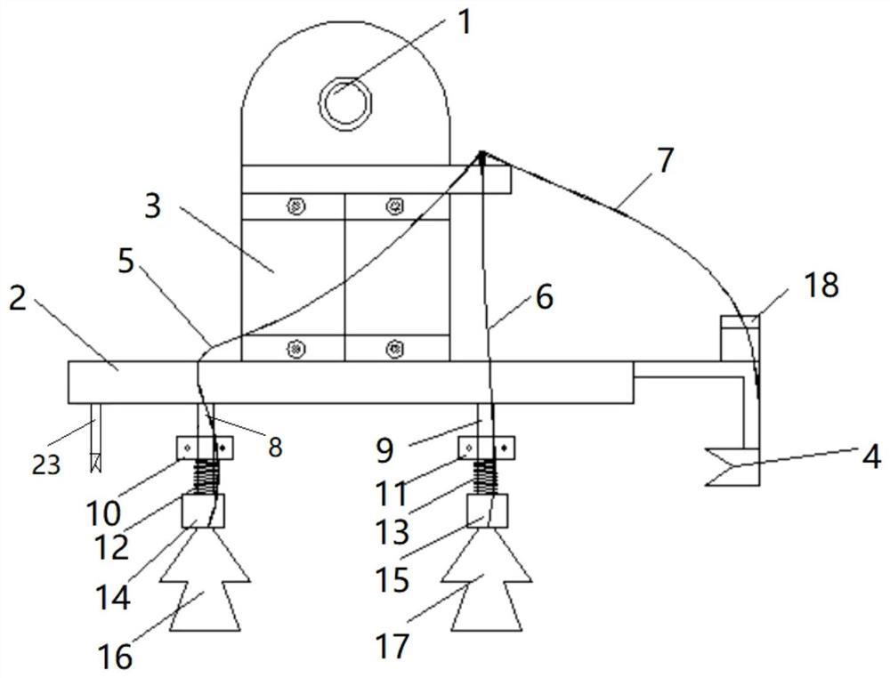
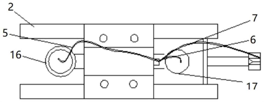
[0027] Such as Figure 1-3 As shown, the present invention includes a rotating shaft mechanism 1, and a cylinder 3 is arranged below the rotating shaft mechanism 1, and the cylinder 3 is connected to the first rubber sucker 16, the second air pipe 7 through the first air pipe 5, the second air pipe 6, and the third air pipe 7 respectively. Rubber sucker 17 and metal collet 4, described cylinder 3 is fixed on the top of table top 2, first connecting rod 8, second connecting rod 9 are connected below described table top 2, described first rubber sucker 16, second rubber The suction cup 17 is connected below the first connecting rod 8 and the second connecting rod 9 .

[0028] Buffer structures are respectively provided between the ...


PUM


Abstract

The invention discloses a manipulator capable of clamping plastic parts. The manipulator comprises a rotating shaft mechanism, an air cylinder is arranged below the rotating shaft mechanism, the air cylinder is connected with a first rubber suction disc, a second rubber suction disc and a metal chuck through a first air pipe, a second air pipe and a third air pipe, the air cylinder is fixed to the upper portion of a countertop, and a first connecting rod and a second connecting rod are connected to the lower portion of the countertop. The first rubber suction disc and the second rubber suction disc are connected below the first connecting rod and the second connecting rod. According to the manipulator, the manipulator is adopted for clamping, thus the safety accident that personnel are scalded due to incomplete cooling of injection demolding and too high temperature is overcome, by means of clamping of the suction discs of the manipulator, the quality problems of product scratch, deformation and the like caused in the plastic injection part clamping process are solved, and the product percent of pass is increased.

Description

technical field [0001] The invention belongs to the technical field of injection molding equipment tools, and in particular relates to a manipulator capable of clamping plastic parts. Background technique [0002] During the production process of plastic parts in the injection molding workshop, the injection molded parts are usually ejected by the injection mold core after mold clamping, injection molding, pressure holding and cooling. Affected by the structure, position and material of the parts to be clamped, the plastic part body Without complete cooling and solidification, the structural strength during demoulding cannot be satisfied, and it is often necessary to select the characteristic position of the plastic part body during the clamping process. [0003] The prior art adopts manual operation and has the following defects: [0004] 1. When the injection molding process is completed and the mold is opened, the injection molded parts are not completely cooled down and...

Claims


Application Information

Patent Timeline
Patent Type & Authority Applications(China)
IPC IPC(8): B29C45/42B29C45/17
CPCB29C45/42B29C45/1769
Inventor 吴定璋林崇徐泽辉胡蔚
Owner DONGFENG VISTEON AUTOMOTIVE TRIM SYST CO LTD
Why Eureka
Try Eureka